|
The Company's Products
This section contains details of some of the many and varied
products that were produced by the company from the early 1900s to the 1940's. At
this time the principal products were rotating electrical machinery, switch
and control gear, static transformers, and rectifiers. |
 |
|
 |
|
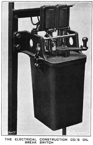
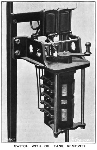
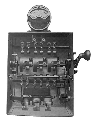
Two motor starting switches from 'The
Engineer' 25th August, 1911. |
|
 |
|
 |
|
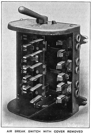
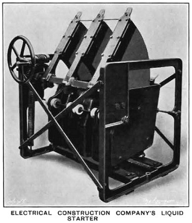
An air break switch and a liquid
resistance switch from 'The Engineer' 1st September, 1911. |
|
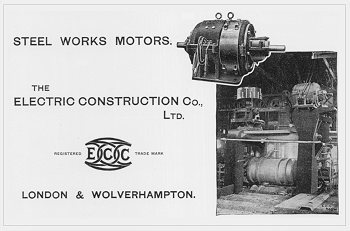
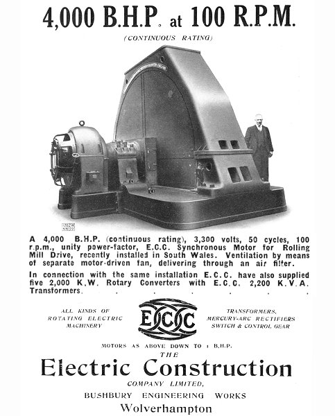
| An advert from 1920 showing an E.C.C. motor driving
a steel rolling mill. |
 |
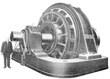 |
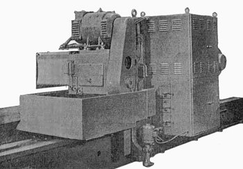
One of E.C.C.'s larger DC motors. It was installed at a
rolling mill and operated in conjunction with a steam-turbine driven
generator.
The motor was rated at 5,000 bhp., at 55 r.p.m. It was
reversible and could reverse direction from full speed in one direction,
to full speed in the opposite direction, in seven seconds. The speed
could be adjusted by varying the current in the field windings. The
maximum speed was 110 r.p.m. |
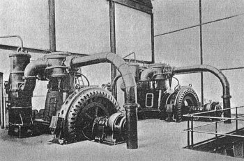
| Two synchronous three phase 600 bhp. motors, that were
used to drive air compressors in a colliery.
The motors also provided
power factor control, so that the equipment operated at its greatest
efficiency. |
 |
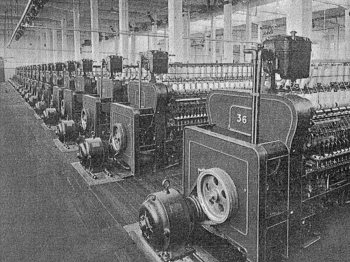 |
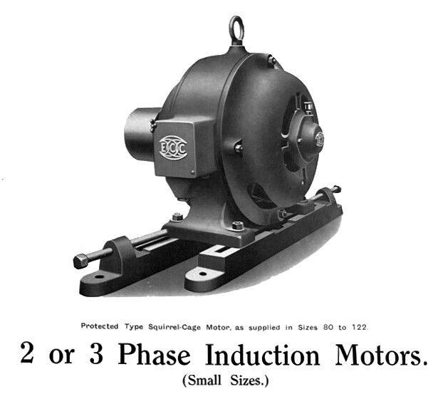
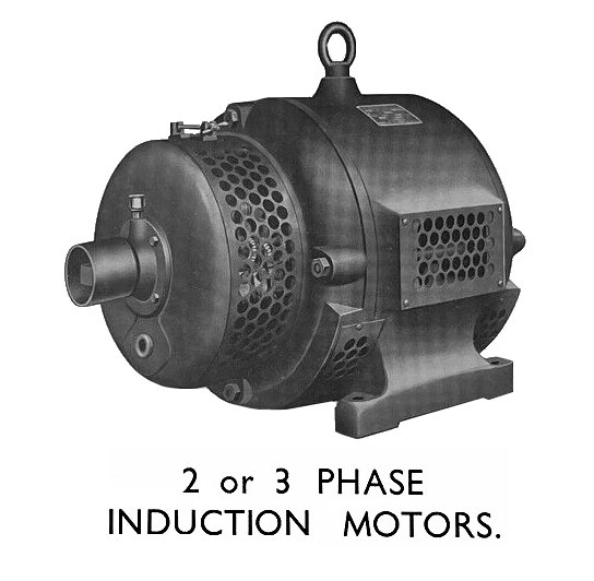
Part of a large installation at a spinning mill.
The
squirrel cage motors were capable of delivering 10 bhp., and were
driving ring-spinning frames. |
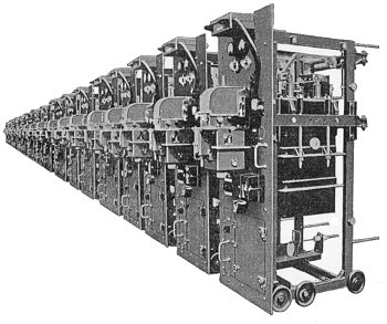
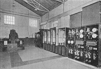
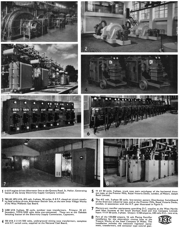
| The company produced switchgear to control all types of
AC and DC motors and generators.
Some of the switchgear, called "trucks"
was mounted on wheels to allow easy access.
The photograph shows part of
60 high tension "trucks" that were installed in a metropolitan borough
power station, to control the outgoing supplies. |
 |
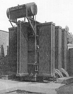 |
The E.C.C. built all types of transformers, up to
10,000 KVA. The photograph shows a 10,000 KVA unit of the outdoor
type, with a conservator and oil-cooling radiators. |
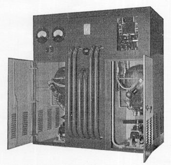
| A 2,200 volts, 65 kW rectifier unit, using two mercury
arc rectifiers, oil-cooled transformer and D.C. switchgear.
It was built
for a Corporation electricity department and delivered an output of
220 volts D.C. at 65 kW. |
 |
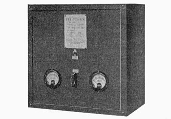 |
A small metal-plate rectifier unit that was built for a
Government department and used to supply a wireless telegraph
communications system. |
| The equipment opposite was installed in a steel works.
It consisted of a 500 bhp. motor, with a speed range of 150 to
350 r.p.m., a 750 kW rectifier unit, which provided 480 volts D.C., from
a three phase A.C. input, of 5,500 volts. There was also a second motor
that was rated at 350 bhp. The control switchgear is on the right. |
 |
 |
An E.C.C. patent varispeed drive, applied to a machine
tool. It consisted of a mercury arc rectifier, variable speed D.C.
motor, and the necessary control gear. |
Early 1930s.
Early 1930s.
Early 1930s.
Motor starting switch from the early 1930s.
An advert from 1936.
| The following article about the E.C.C. 'Varispeed' system
appeared in 'The Engineer' on 8th November, 1946: |
|
A
Variable-Speed Power Drive
The problem of providing
variable-speed power drives is of considerable interest,
not only because it affects an ever-increasing number of
manufacturing processes, but because the solution
involves a choice between many methods, both mechanical
and electrical.
Amongst the more common electrical
methods of obtaining a variable-speed drive are change
pole induction motors, Ward-Leonard sets, AC. commutator
motors of various kinds, and, where a DC. supply is
available, the shunt-controlled DC. motor. Because of
its excellent speed characteristics, the shunt-wound DC.
motor commends itself to many engineers, but its use
nowadays tends to be restricted because of the modern
preference for individual drives in production machines,
coupled with the adoption of standard three-phase AC.
supply throughout this country. |
 |
Particular interest therefore
attaches to the "Varispeed" drive developed and
manufactured by the Electric Construction Company,
Limited, Bushbury Engineering Works, Wolverhampton,
using a standard DC. motor supplied from AC. mains
through the medium of a mercury arc rectifier. The
rectifier supplies DC. separately to the armature and
field system of the motor, the two supplies being
independently variable. By this arrangement the speed
can be varied over a very wide range, as much as 1000 to
1, providing constant torque throughout this speed
range.
A simple single-phase circuit,
illustrating the principle of the system, is shown in
the accompanying diagram, in which the AC. supply is
connected to the primary of a transformer having two
secondary windings. The main secondary winding supplies
the two main anodes of a mercury arc rectifier, which
converts AC. to DC. for supplying the motor armature.
The auxiliary secondary winding is connected to two
auxiliary anodes to provide DC. for the motor field.
A maximum speed range of about 4 to 1 can be obtained
from a DC. motor of normal design by varying the shunt
field current while keeping the applied armature voltage
constant. Under these conditions the output horsepower
remains approximately constant throughout the speed
range, for the torque falls as the speed increases, that
is, as the field current is reduced. |
|
If, on the other hand, the shunt
field current is kept constant while the armature
voltage is varied, the speed of the motor varies
approximately as the applied armature voltage. By
varying the voltage supplied to the armature from zero
to maximum, an infinitely great speed range can be
obtained with constant maximum torque from the motor,
since the field current remains at its maximum at all
speeds. Maximum horsepower is therefore developed at
maximum speed.
Since the majority of drives
require maximum horsepower at maximum speed, with the
torque remaining constant at its maximum value
throughout the speed range, it is usual to use armature
control, which considerably reduces the overall size of
the motor. A further reduction in cost results from the
fact that armature control normally eliminates the
necessity for separate starting gear. The speed control
gear can be used to start the motor smoothly from rest.
A combination of armature voltage and shunt field
control can be applied with advantage in many instances
where maximum torque is required at some speed less than
full speed, or where some compromise between constant
torque and constant horsepower is required.
Assuming, however, that the field
is maintained constant, the motor speed will depend upon
the armature voltage supplied from the rectifier valve.
This voltage can be varied by anyone of several methods,
depending entirely upon the kind of drive and the speed
range required. Since the ratio of the DC. voltage to
the AC. voltage of the rectifier is fixed, a variable
DC. voltage can only be obtained by applying a variable
AC. voltage to the rectifier. In general, there are
three methods whereby the AC. and therefore the DC.
voltage can be controlled.
An E.C.C. 'Varispeed' drive for a draw bench.
The first method requires an
on-load tap-changing switch to vary the main secondary
voltage from the transformer in a predetermined number
of fixed steps. The second method employs an induction
regulator to vary the main secondary voltage smoothly
over a range designed to suit the speed range of the
motor.
The third method makes use of grid
control between the anodes and cathode of the rectifier,
giving smooth control over the DC. output voltage and
the speed of the motor. Normally the first method is
used for small machines, where a number of fixed speeds
is acceptable. With larger machines, when smooth speed
variation is important, either of the remaining two
methods can be used.
There are therefore three essential
components in the equipment; the transformer and
controller, the rectifier cubicle, and the motor itself.
All of these components can be mounted separately, which
allows considerable flexibility in layout. Wiring is
reduced to a minimum, since there are only three wires
between the rectifier cubicle and the motor (without any
intervening starter), and the fine wiring between the
rectifier cubicle and the controller.
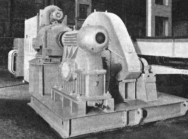
A typical "Varispeed" installation
is depicted in the accompanying engraving, which shows a
267 hp. shunt-wound DC. motor driving an automatic draw
bench. The rectifier cubicle and the transformer can be
seen behind the main motor. This equipment, which is
entirely automatic, gives the motor a speed range of 0
to 1200 rpm. providing constant torque throughout this
range. An interesting point is the use of a forced
ventilating system which accounts, in part, for the
small size of the variable speed motor.
Since acceleration is completely
smooth throughout the speed range, the accelerating time
can be reduced to a minimum. The system lends itself
satisfactorily to automatic control, reversing duty,
dynamic braking, and rapidly variable acceleration.
Throughout the speed range the efficiency and power
factor of the system are high. It will be noted that the
rectifier has no excitation losses, since the excitation
is used to supply the field of the motor, resulting in
an appreciable gain in efficiency. |
|
|
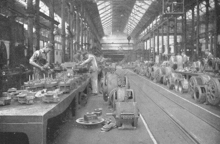
Assembling motors in 1938. |
|
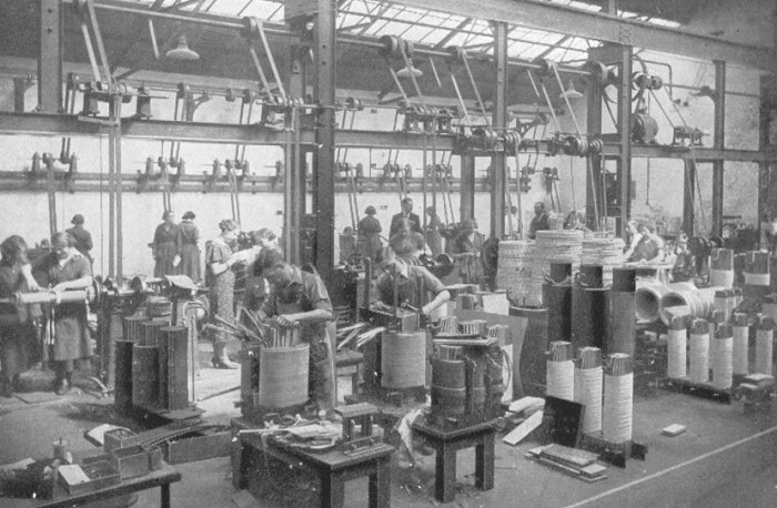
Assembling transformers in 1938. |
|
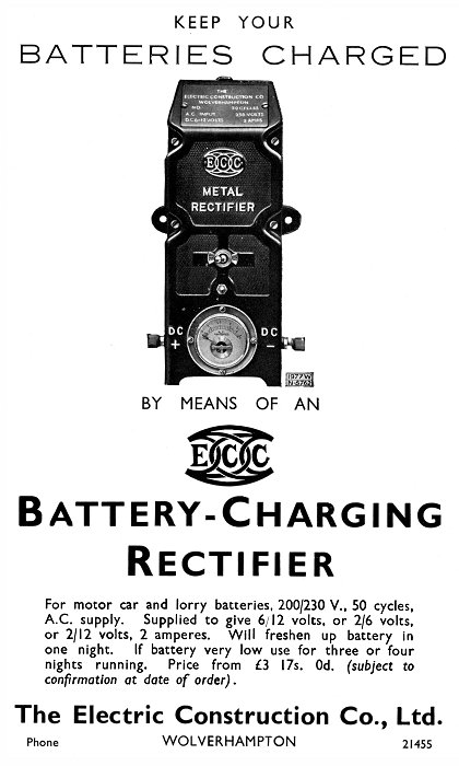
An advert from 1942. |
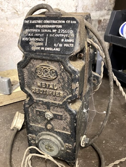
An E.C.C. battery charging rectifier. Courtesy of
Tamlin Roberts.
An advert from 1956.
|
|
|
|
|
| Return to
Bushbury Works |
|
|
|
Proceed to the
Later Products |
|