The E.C.C.
When the new Corporation was formed, it purchased and
amalgamated the following companies and their patents:
1). Elwell-Parker, Limited. Employing 400
people with a large order-book.
2). The Elecrical Power Storage Company Limited, and their Millwall
factory, together with the company's many electrical power storage
patents.
3). The Railway Electrical Contractors Limited, and their patents
and contracts for train lighting.
4). The Julien Patents for Electric Traction, the Sprague Patents
for Electrical Traction and the Transmission of Power.
The starting Capital of the Corporation was £500,000
in 50,000 shares of £10 each. Numbers 1 to 100 inclusive were Founder’s
Shares. The new concern was incorporated on 7th June, 1889,
and it was decided to build a new works on the land already purchased by
Elwell-Parker at Bushbury, along with some adjacent land. The new works
were erected at a cost of £10,000 on the 24.5 acre site. When the
building work was complete, the staff and machinery from Commercial Road
were moved to the new site.
The directors included:
Sir Henry C.
Mance, C.I.E. (Director of the West African Telegraph Company)
Sir Daniel Cooper,
Bart., C.M.G. (Chairman of the Electric Power Storage Company Ltd.)
Mr. John Irving
Courtenay (Managing Director of the Electric Power Storage Company Ltd.)
Sir Douglas Fox
(Member of the Council of the Institution of Civil Engineers)
Sir James Pender,
Bart., K.G. (Director of the Eastern and South African Telegraph
Company)
George Dibley
(Director of Andrew Handyside & Company Limited)
Sir Robert Fowler,
Bart., M.P. (Director of the Metropolitan Electric Supply Ltd.)
Henry P. Holt
(Crossley Brothers Ltd, Manchester. Director of Elwell-Parker Ltd.)
Joseph Moseley
(David Moseley & Sons, Manchester. Chairman of Elwell-Parker Ltd.)
John B. Verity
(Director of the Metropolitan Electric Supply Ltd.)
Thomas Parker was Works Manager and the engineer was J.E.H. Gordon, who
was well known for his work on connection with the early electric
lighting at Paddington Station.
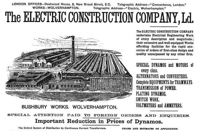
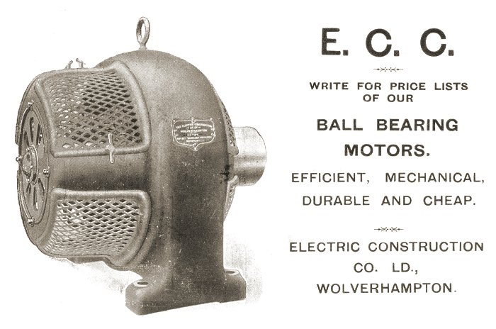
The company produced almost every conceivable piece of electrical
equipment. Some of the company’s products were alternators, dynamos,
motors, accumulators, ammeters, voltmeters, duplex dynamos,
transformers, resistance frames, magnetic transformer switches,
switchgear, knife switches, continuous current rotary transformers,
battery charging transformers, electrical switchboards, high voltage
switches, voltmeter switches, arc lamps, and gas tight motors for
electric pumps and electric cranes. The company also produced a 52
passenger tramcar for the Bournemouth Tram Depot, a 9h.p. narrow-gauge
electric locomotive, an alternator for Manchester Square Station, a 34
passenger accumulator tram for Birmingham Tramways, 15h.p. tramcar
motors for the South Staffs Tram Co. and electric colliery locomotives.
| In 1888 Elwell-Parker, Limited developed an
electrically powered tram for the Birmingham tramways. Due to its
success, E.C.C. got the order to install an electric accumulator
tramway in the city. |
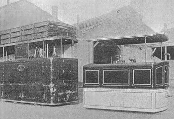
An E.C.C. electrical accumulator locomotive |
The Corporation got off to an excellent start under the chairmanship of
Sir Henry Mance. The works were operating at full capacity and orders
flooded in, including a further order from the Birmingham tramways,
following the successful running of the Elwell-Parker prototype. In the
battery-powered vehicles, the accumulators were placed under the
passenger's seats, and a portion of the gross profit was absorbed in the
settlement of claims from passengers, whose clothing had been splashed
by acid.
In 1890 the company carried out the electrification of Sir Daniel
Cooper's Tudor Mansion, Grim's Dyke. Two E.C.C. 26 seater omnibuses were
running in London in 1891. They ran from Charing Cross to Victoria
Station and were powered by two large electric motors, and 72 lead-acid
batteries. They had wooden wheels with iron tyres. The company also
built a number of battery powered, 14 seater, single decker buses, for
the London Electric Omnibus Company.
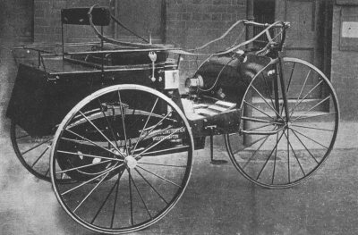 |
The company's most famous
motor car was the Electric Dog Cart, which was built in 1896. |
Within four years the new company found itself in deep trouble and was
voluntarily wound up in July, 1893. It seems that there was a lot of
dissension amongst the Board of Directors, one of whom later was
convicted of fraud. The company was reconstructed as the Electric
Construction Company Limited. Sir Daniel Cooper was Chairman and Mr.
P.E. Beachcroft, J.W. Barclay and J. Irvine Courtenay joined the Board.
The Company Secretary was Mr. James Gray and Mr. Emile Garcke joined the
Board to be responsible for the reconstruction of the commercial side of
the business.
| The company produced an overhead wire system for the
electrification of the South Staffordshire Tramways and a little
while later installed a similar system at Hartlepool. The company
also carried out the electrification of the Liverpool Overhead
Railway, which was opened by the Marquis of Salisbury on 4th
February 1893.
In 1894 Thomas Parker left to start his own company. He was replaced as
Works Manager at Bushbury, by Mr. A.B. Blackburn. |
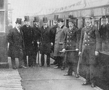
The opening ceremony of the Liverpool
Overhead Railway. Thomas Parker is on the extreme left. |
|
An advert from 1893 listing some of the
company's more important installations.
|
The E.C.C. installed a number of electricity supply stations that were
based on a high voltage D.C. system. The central generating station
produced the high voltage, which was converted to 200 volts D.C. by
motor-generators, which were housed in sub-stations. The first
installation was at Oxford and used a 2,000 volt high tension line. This
became known as the Oxford System. Following its success, similar
systems were installed at Wolverhampton, Birmingham, Charing Cross,
Chelsea, Sydenham and Shoreditch.
The company also built the switchgear for the Burnley Electric Light
Station, the third rail tramway system for the Portrush and Giants
Causeway Tramway Company and tramways in Brussels and Melbourne.
|
The
Crystal Palace Electrical Exhibition. The Engineer, 1st
April, 1892.
The present exhibition at the Crystal
Palace will mark the successful operation of one of the most
practical modern schemes for the distribution of electric
current over wide areas. The continuous current transformer
has here asserted itself, and proved that with carefully
worked out details in construction, and in the system with
which it is
used, it is a most trustworthy and
efficient means of securing the advantages of a high tension
distribution with a continuous current supply. No
undertakers who find themselves called upon to extend their
low tension mains into remote suburban districts need fear
that because they do not happen to be using alternating
currents, they must either bear the cost of additional
stations to feed the network or sink excessive amounts in
mains.
The entire system has been worked out
on a practical basis by the Electric Construction
Corporation of Wolverhampton under the guidance of Mr.
Thomas Parker, the works director, and one of the most
pleasing exhibits in the exhibition is to be found in the
stand of this Corporation in the Machinery Court, containing
as it does machines of such high-class construction, and
controlling apparatus so well suited to the requirements of
the system.
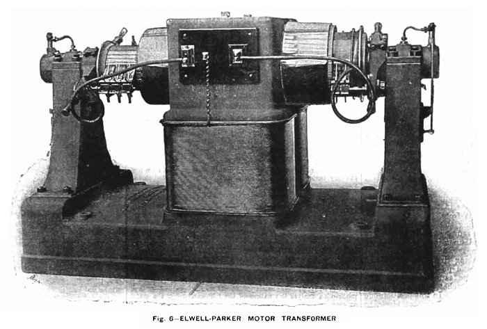
The largest machine in this stand, Fig.
6, is a continuous current transformer or motor transformer,
identical in size and output with the ten machines used
inside the Palace for the supply of current to exhibitors.
It is to be regretted that it was found necessary to fix
these machines so far out of sight underneath the Palace, as
otherwise their full display in operation would have
considerably added to the practical interest of the
exhibition.
We have already explained the working
of the machines in the Palace, which receive current at
1,000 volts pressure from the Crystal Palace and District
Electric Supply Company’s Station at Sydenham, one and a
quarter miles distant, and transform it down to a pressure
of 110 volts for exhibitors. The complete system of
distribution by these motor transformers for town lighting,
as now adopted at Oxford, will be understood by reference to
Fig. 7.
In the first place there is the
generating station, the site of which is selected with
reference to good water supply and economical facilities for
delivery of coal. In this station are installed the
necessary engines and boilers, together with the electric
generators and their exciters. As the area of lighting
extends, more generators can be added, their manipulations
in parallel being perfectly simple. These produce current at
1,000 volts pressure, which is delivered by all the machines
on to one pair of bars in the station, known as omnibus
bars, or shorter, bus bars. From these the current proceeds
along the high tension mains to the most central point in
the district of supply, at which is located a central switch
station.
From this station is controlled the
working of all the transformers used in the system, these
machines being located in sub-stations situated radially
around the switch station at points most favourable for
feeding the low tension network of supply, and keeping the
electric pressure uniform throughout. At the switch station
there is a pair of omnibus bars receiving the high tension
current from the generating station, and from which the same
current is, through double pole switches, connected onto the
feeders supplying the motor transformers at the
sub-stations. For the complete control of all the
transformers only one man is required in the switch station.
The voltmeters in this station show the
pressure on the town supply network at all the sub-stations,
and as the load increases in any district, the pressure is
kept up by switching on an additional transformer located in
that district. Although the sub-stations where the
transformers are fixed are at various distances away from
the switch station, the switching in or out of these
machines controlled by one man at the above station with
perfect certainty and ease.
In performing this operation the first
thing to do is to close the two-pole switch which conveys
the high-tension current to the transformer. The current,
which passes through a considerable resistance before
leaving the station, passes into the armature of the machine
on the high-tension side, and excites the field through a
few turns of thick wire in series. The brushes on both
commutators are kept permanently down, and need no
alteration of lead for changes of load, as the reactions of
the two armatures neutralise one another. Once the
excitation of field is started, the machine starts, at first
quickly, but the shunt field rapidly building up, the speed
soon decreases again, and is then brought up to the required
amount by reducing the main resistance in the switch
station. So far the transformer is started, but the
secondary winding on the armature is not yet put in
connection to feed the supply mains. This is done at the
switch station by the simple act of momentarily closing and
opening a switch which short-circuits the voltmeter. This
causes a current to flow through an automatic circuit closer
fixed with each transformer in the sub-station.
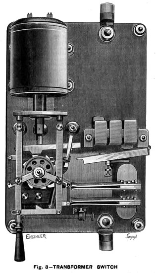
This apparatus, shown in the figure,
consists primarily of an iron-clad electromagnet, the
exciting coil of which is included in the circuit of the
voltmeter at the switch station. The resistance being small
does not interfere with the voltmeter readings, and,
moreover, by short circuiting the voltmeter in the switch
station for an instant, a large current from the supply
mains flows through the coil, causing the armature of the
magnet to be drawn up. The armature carries two pawls lying
on a ratchet wheel, and upon its being attracted upwards,
the left-hand pawl engages one tooth and moves the ratchet.
Again, on breaking the short-circuit
the armature falls, and the right-hand pawl engages, forcing
the wheel round further in the same direction. The double
operation moves the ratchet wheel and cam through one-eighth
of a revolution. In this position one tooth of the cam bears
down on the contact block, so completing the low tension
circuit from the transformer to the mains. The load on the
mains is equally divided between the transformers at work,
but in case of short circuit or any accidental stoppage
which would cause an undue rush of current into the machine,
an automatic cut-out, shown at M is fixed in connection with
the above apparatus. The armature of the electromagnet M
would in such an event be drawn up and strike the cam,
shifting it round and disengaging the tooth from the contact
piece S, thus breaking the circuit.
Similarly, as the load decreases, the
various transformers can be severally disconnected from the
supply by the operator at the switching station. Once
closing and opening the voltmeter switch shifts the cam
another eighth round, and allows the contact piece S to rise
and break circuit.
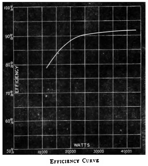 |
By this arrangement the transformers are only
used as the load requires, and are therefore, for
the greater part of the working time, near their
full load; and as the efficiency of these machines
reaches 92 percent when delivering their full load
of 40 kilowatts, and 87 percent at half load, see
curve, Fig. 8, it will be seen that the whole system
is worked with great economy. The only regulation
required in the generating station is the adjustment
of the strength of exciting current supplied to the
generators, the pressure, as indicated by a
voltmeter on the omnibus bars in the station, being
maintained constant by this means. The exciting
current is regulated by resistance in the shunt
field of the excitors, of which there is a separate
machine for each generator. |
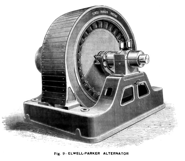
The Corporation have also carried out
several important contracts in alternating current plant. We
illustrate the Elwell -Parker alternator, Fig. 9, of 80
kilowatts, as exhibited in operation at the Palace. The
armature is a stationary external ring, built up of soft
iron rings, to the inside surface of which are clamped the
coils. The latter are twelve in number and composed of
copper strip, the edges being placed radial to the machine.
These are held by wooden clamps bolted round the ring on
each side. The field magnet, with the same number of coils,
mounted on cores and yoke of solid forged iron, rotates
inside the armature. The machine being high-tension, the
armature is externally cased-in with a wooden cover, and the
terminals of the machine are protected under a portion of
this cover, kept under lock and key. The wires leading from
these terminals are also taken underneath the bed of the
machine in casing through the concrete, so that complete
immunity from danger is attained.
Alternate current transformers of 2 and
4 horse power output are also shown in Fig. 10. These are of
very simple construction, the two circuits being first bound
together and afterwards encased around with soft iron plates
made in the form of the letter L and built up on each side
of the coils. The two rows of discs are then clamped
together by bolts passing through cast iron end pieces.
The Corporation also exhibit a new
pattern of adjustable resistance, sets of cut-outs fitted in
porcelain boxes, and a high tension automatic switch used in
connection with the above transformers. |
|
|
Electric Lighting in Oxford. The
Engineer, 1st July, 1892.
On Saturday, June 18th, the electric
current was switched on for the first time to the City of
Oxford, by the Oxford Electric Company, and a large party
had been invited to a dinner given at the works in honour of
the occasion. The arrangements were very satisfactorily made
by Mr. George Offor, the secretary of the company. We have
referred previously in our issue of April 1st last to some
of the features of the system employed, and are now able to
give a full description of the plant.
It was found impossible to obtain a
suitable piece of ground for the works near the centre of
the city, a piece of land was therefore acquired at Osney
upon the banks of the River Isis.
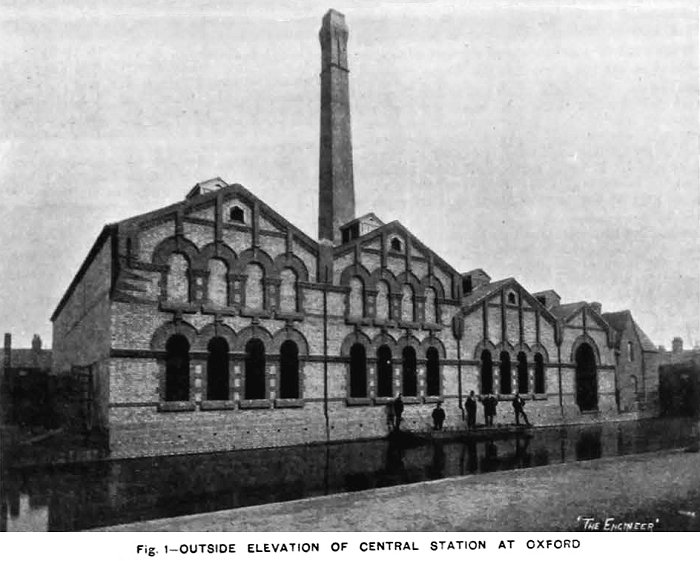
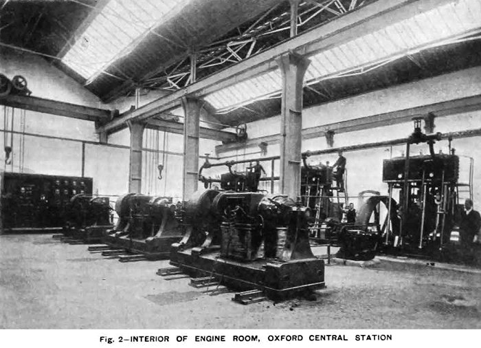
The outside of the building, which are
of a neat design in brick, is shown in Fig. 1. The interior
of the engine room is shown in Fig. 2, from which it is
evident that there is ample room for more plant. This
position will enable the company to charge electric
launches, which will be an important source of revenue, and
the works are kept away from the better parts the town.
The
system adopted is that of high-tension continuous currents,
with dynamotors or current transformers, which produce
currents of low pressure for the network. The dynamos at the
generating station produce the current at a pressure of
1,000 volts, and this is transformed down at the sub
stations to a pressure of 100 volts. Fig. 3 is a plan of the
part of the city in which the substations are placed, and
the mains already laid along the streets are shown.
The
contractors for the whole work are the Electric Construction
Corporation, of Wolverhampton, and it has been carried out
under the supervision of Mr. Thomas Parker, the managing
director. The building is a well built structure of brick,
designed by Mr. Brevitt, of Wolverhampton, and the builders
were Messrs. Kingerley, of Oxford.
It is divided into two main sheds,
separated by a brick wall. The engines and dynamos are
placed in one part, and the boilers in the other, and all
the plant is on the ground level. The engine room is thus
kept perfectly free from coal dust. Three steel boilers of
the locomotive type are at present installed; these were all
built by Messrs. J. and H. McLaren, of Leeds; a Green's fuel
economiser is placed in the main flue and a suitable by pass
is arranged so that gases may pass direct to the chimney if
needful.
The engine room is well lighted from
above. The steam pipes are arranged upon the ring system, so
that in case of breakdown, as little as possible of the
plant would be affected. Stop valves are placed between each
two engines, and the bends are all of copper. Three engines
are now put down, and these are of the inverted
triple-expansion type, built by Messrs. J. and H. McLaron
and Co. By the courtesy of the makers we are enabled to give
the results of tests which were carried out at the works by
Mr. Wilson Hartnell, Professor Goodman, and the inspecting
engineer, Mr. Watson. The sizes of the cylinders are:-
high-pressure, 9in. diameter, intermediate, 14·25in.,
low-pressure 22·5in. diameter, by 24in. stroke.
Two trials
were made, in one of which it will be observed the steam
jackets were used, an in the other were not used. We may add
that the high-pressure and intermediate cylinders are jacketted with steam at boiler pressure, and are drained
through a McDougal steam trap into the hot well. The
low-pressure cylinder is not jacketted. The McLaren
automatic governor is placed inside the fly-wheel upon the
shaft itself, and it works direct on to the high-pressure
slide valve, which is not balanced in any way. The governor
is self-locking, and is therefore not affected by any
friction on the slide valve. The engines run very steadily,
and all danger of the governor being put out of gear by the
breaking of a belt is obviated. The surface condenser
is fitted with brass tubes and tube plate; the tubes are
⅞in. outside diameter, and there is 382 square feet of
cooling surface.
The air pump is 11½in. diameter, the
circulating pump 10in. diameter, and the feed pump 1¾in.
diameter, all three having a stroke of 14in. The pumps are placed behind the
condenser, and are worked by levers from the intermediate
engine. The crank shaft is of forged steel, 5¼in. diameter,
the crank pins 5½in. diameter, and the engines are
thoroughly well finished. Each of the engines is provided
with a heavy fly-wheel, and drives a dynamo by means of
belting; two of the belts are of the usual double-sewn type,
and the third is a Gaskin link belt.
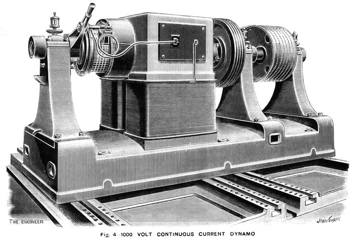
The three dynamos, one of which is
shown in Fig. 4 are all similar, and were built by the
Electric Construction Corporation; each develops 1,080 volts
and 80 amperes, when running at 400 revolutions per minute.
The dynamos are provided with an extra bearing outside the
driving pulley, and each is excited by a small Elwell-Parker
dynamo, driven from a rope pulley keyed on to the shaft of
the main generator. The exciters give 135 volts, and can
thus be used to charge the accumulators which are used for
lighting the central station.
The electro-motive force of the dynamos
can be regulated from 1,100 volts at full load to 1,000
volts at light load, by means of resistances placed in
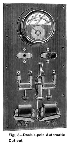
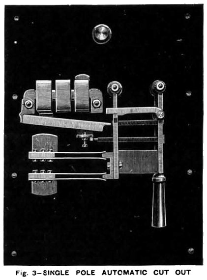
circuit with the exciters. In the circuit of each dynamo is placed
a double pole automatic cut-out, shown in Fig. 5 which
protects the dynamo in the event of any excessive current,
and is reset by hand, but it is so arranged that the cut-out
cannot be held on. The dynamos are all connected in parallel
to two common omnibus bars upon a switchboard at the works.
The foundations for the engines are of
a solid block of concrete, and that for the dynamos another
solid block, weighing about 100 tons each, and about 11ft.
deep. Air spaces are left round the blocks to diminish
vibration.
The switchboard at the works is very
simple, and consists of three panels, each of which is
similar to Fig. 5, and carries one ammeter for the high
tension circuit, one for the exciter circuit and the
knocking-off switch previously alluded to.
 |
Two overhead cranes, each capable of
lifting six tons, are provided in the engine house, and a
battery of fifty three E.P.S. cells is used for the lighting
of the station. By means of this battery and of that at the
chief sub-station, it is possible to shut down altogether at
the works for six to eight hours in winter, and twelve to
sixteen hours in summer. At the time of our visit, Mr.
McLean, the engineer in charge, had placed a dynamotor in
the works in order to light up about five arc lamps of
fifteen amperes each, and 370 eight candle-power lamps.
Current was also supplied for the electric cooking, which
formed a feature of the dinner.
From the generating station run out two
pairs of heavily insulated Silvertown cables, each
consisting of 37/14 copper wires; these are laid in
cast iron pipes, and are carried a distance of about
one mile to the distributing station at Broad Street
marked No.1 on the plan, Fig. 3.
The system of working is clearly shown in
diagram-Fig. 6 which we published in a previous
issue. It will be seen that the dynamos are coupled
to two omnibus bars at the generating station, and
thence run the high-tension mains to the central
switch station, whence all the other sub-stations
are controlled. |
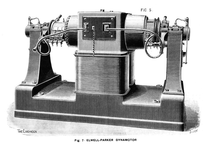
At each of the
stations, Nos. 1, 2, and 3 on the plan Fig. 3, is placed a
dynamotor, such as shown in Fig. 7, which transforms the
pressure from 1,000 volts to 110 volts, and gives out a
current of 360 amperes when fully loaded. The efficiency of
these machines is very high, being 92 percent when fully
loaded, 89 percent at three quarters load, and 87 percent at
half load. The main winding is a shunt to the low-tension
side, and there are a few turns on the magnets in series
with the high-tension armature. The oiling arrangements are
very complete. The end of the armature shaft is provided
with a cam, which actuates the piston of a small oil pump
which feeds the bearing; the oil passes away through a
filter to the oil reservoir, and is used over again. It is
thus possible to run for some days without attention. The
brushes upon the commutator are of copper gauze.
An accumulator of 114 cells of the L.
31 E.P.S. type is installed here, and the cells are arranged
in four groups, two of thirty-eight cells and two of
nineteen cells. They are charged in three groups of
thirty-eight cells each, and are discharged in two groups,
each consisting of thirty-eight and nineteen cells in
series, and are capable of supplying a current of 120
amperes for eight hours.
|
Voltmeters are provided at the central
switch station, which show the pressure at each of the
sub-stations, and all the transformers can be controlled by
one man. In starting a transformer the high-tension circuit
is first closed through a resistance in order not to injure
the armature windings.
The dynamo field is then excited by a
few coils in series. The dynamo part then begins to produce
current, and the resistance is gradually taken out of the
high-tension circuit.
In order to put the transformer into
circuit with the low pressure network, a special apparatus
has been designed, shown in the diagram and also in Fig. 8;
this instrument is placed at the sub-station and is designed
for 400 amperes.
It consists of a long-pull electro-magnet,
which actuates a ratchet wheel and controls the switch. It
is actuated by merely closing and opening a switch which
short circuits the voltmeter on the pilot wire. One of the
wires to the voltmeter is wound round the long-pull magnet,
and the feeble current passing to the voltmeter under
ordinary conditions is not sufficient to attract the
armature, but by closing the switch the voltmeter is cut out
of the circuit, and the long-pull magnet acts; the switch is
then opened, the heavy armature drops, and the double
movement causes the switch which connects the low-tension
network to the transformer to close. In cases of accidental
overloading, an automatic cut out-shown in Fig. 5 opens the
circuit.
|
 |
The present capacity of the entire
plant is 12,000 lamps of 32 watts, and 15,000 lamps could be
wired. The low-tension mains were manufactured and laid by
Callender's Bitumen Telegraph Company, under the
superintendence of their engineer, Mr. W. Douglas Reid.
Those cables are of two sizes, half a square inch and a
quarter of a square inch section, and are of the
lead-sheathed type, armoured with two layers of steel tape.
These cables are simply laid in a trench under the footway,
at a depth of about 18in. They are laid in lengths of from
150 to 200 yards, and are connected together in cast iron
joint-boxes by means of copper connectors. The box is then
run in solid with bitumenised wax compound. Disconnecting
branch boxes are provided at different points in the network, so
that any section or street can be cut out without in any way
interrupting the supply to the rest of the network.
House service wires are connected in T
boxes by means of T copper connectors. These boxes and
connectors are so made that the cable is not out, but is
simply bared down to the copper strands and the connector
put on and soldered. The box is then run in solid with the
bitumenised wax compound. The small service wires are of two
sizes, seven fourteenths and twelve fourteenths, lead
sheathed and armoured. The arc cables are similar, but seven
sixteenths. The whole installation is a very interesting
example of the possibility of using high-tension continuous
currents for large areas.
|
|
High Tension Continuous Current Switchgear. The Electric
Construction Corporation, Wolverhampton. The Engineer 31st
March, 1893. |
|
The switchgear illustrated by the
accompanying engravings are those used by the Electric
Construction Corporation, Wolverhampton, for their high
tension continuous supply system, as used at Oxford, and at
Sydenham.
The system consists in supplying a
system of distributing mains with current from a number of
motor generators situated at sub-stations, these being
supplied with current by high tension feeders run directly
from switchboards at a central station. Each transformer has
a separate feeder, and a pair of pilot wires also come back
from each sub-station. The starting, stopping, and
controlling of the motor generators is carried out from the
central station.
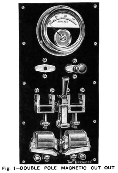
Fig. 1 represents a double-pole
automatic magnetic cut-out and main switch, which is coupled
on to the main omnibus bars at the central station, and from
which feeders running between the transformers are
connected.
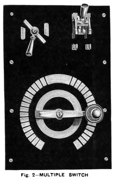
Fig. 2 represents a multiple contact
switch for cutting resistance in or out of the high-tension
feeder circuit. To start a transformer the multiple-contact
switch - Fig. 2 - is turned over, so that all resistance is
in circuit. The automatic cut-out- Fig. 1 - is then put on
so that the high tension current passes to the motor
generator at the sub-station. |
 |
 |
A few turns of thick wire wound round
the magnets in series with the feeders gives the necessary
magnetic field, enabling the motor generator to start. The
secondary or low tension then gradually magnetises the motor
generator field up to its full strength by a shunt across
the low-tension armature.
The starting resistance, which is
connected to the right-hand side blocks of the multiple
contact switch, Fig. 2 - is then taken out of circuit. The
small quick-break switch, shown at the top left hand corner
-Fig. 2 - is then closed, which short circuits the pilot
wires running back from sub-station, and one of these, wound
round a pot magnet, actuates a special transformer switch,
which connects the low-tension armature of the motor
generator on to the distributing mains. This switch is then
again broken, as only a momentary current is necessary, the
switch being held in either an on or off position by
springs.
A voltmeter is connected across the
pilot wires so as to indicate the electro-motive force on
the network at the feeding point. The regulation of this
electro-motive force is carried out by the left-hand blocks
of the multiple-contact switch - Fig. 2 - cutting resistance
in or out of the circuit. |
| Fig. 3 represents a single-pole automatic magnetic
cut-out, as is used at Oxford on the low tension of
transformers, situated at the central station, where they
can be reset by hand.
These cut-outs break circuit in event of an excessive
current being demanded by a short circuit on the mains.
The magnet is compound-wound, so that in the event of one
of the motor generators failing to give proper
electro-motive force, the current passing back from the
mains cuts out at a much smaller number of amperes, so as
not to cause an excessive demand from any other motor
generators that may be on the circuit, which is a thing that
always happens where ordinary fuses are employed; any fault
due to one machine failing to give its electro-motive force
usually melting the fuses of other machines that may be
connected in parallel on to the same circuit, owing to the
large current required to cut out the machine that has
failed. |
 |
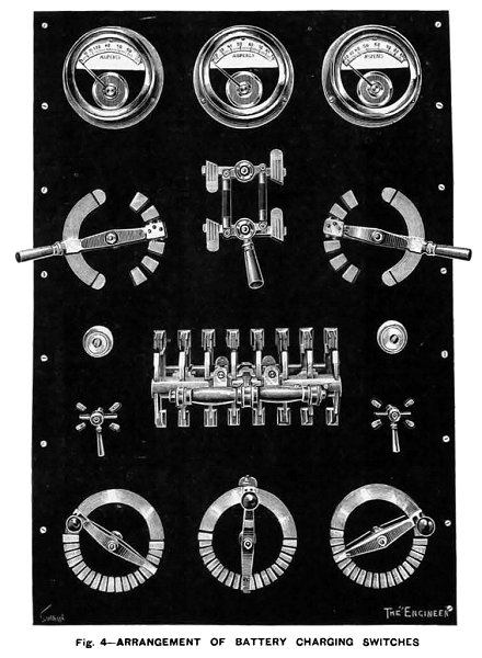 |
Fig. 4 represents an arrangement for charging a battery
of accumulators from distributing mains. As these are kept
at a constant electro-motive force, it is necessary to
cut-up the battery into sections for charging. At Oxford
there are 120 cells. These are charge in sets of 40 each,
discharging in sets of 60 each. A throw-over switch in the
centre of the board enables this alteration to be effected.
Three multiple contact switches at the bottom of the board,
and three ammeters at the top, are connected, one in each of
the three series when charging.
Two multiple contact switches enable the number of cells
in the discharging circuit to be regulated, and a
double-pole switch is provided for cutting off the
accumulators entirely. The two-way switches are provided for
connecting the voltmeter across one or other of the
batteries. |
|
In1895 the E.C.C. completed an order for the switchboard and
transformers for St. Panchras Station, engines, exciter and switchboards
for the Oxford Electric Light Station. In the same year the company
built and installed the switchboards, switchgear and generators for the
Wolverhampton Generating Station, and generating plant for Oxford
Central Station. The company also installed electric lighting at
Wightwick Manor, which was the home of Charles Mander, whose company
manufactured paints, varnishes and inks. The installation consisted of a
steam driven generator, which supplied 100 volts D.C. for the lamps. A
set of lead-acid batteries was added at a later date.
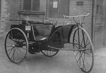
The E.C.C. experimented with motor cars, the most famous of which, the
Electric Dog Cart was built in 1896.
| Reins were used to steer the vehicle because Mr. A.
B. Blackburn who was works manager enjoyed horse riding and so the
vehicle had to be as similar as possible to a horse-drawn one. The
operation of the motor controller was by sliding seat. It was said
by Walter "Wattie" Wall who was an old employee who often drove the
dog-cart, that the arrangement worked quite well when the movement
consisted of sliding the seat backwards, but not so well when it was
necessary to pull it forward. |
Another view of the Electric Dog Cart. |
This difficulty was overcome by screwing a half egg shaped wooden block
to the seat. It rested between the driver's legs and provided the
necessary lock between him and the seat. The vehicle had an interesting
career including a drive through London with the late Duke of Fife as
passenger. In 1896 the car was entered in a race for self-propelled road
vehicles, from the Crystal Palace, London to Birmingham. This was
organised by 'The Engineer' magazine, and there was a 1,000 guinea prize
for the winner. There were 72 entries, but on the day there were only
five runners, and so the race was cancelled. The car however, was highly
commended. The car was eventually broken-up at the works. The motor was
used for many years to drive an ash-hoist in the E.C.C. boiler house.
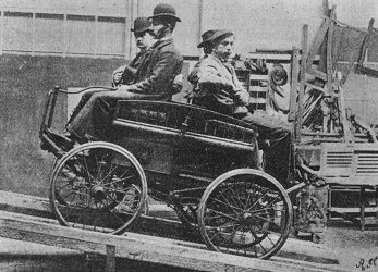 |
The photograph opposite, shows
an 1897 petrol car, being tested on a 1 in 6 gradient at the
Bushbury works.
Photo courtesy of the late Jim Boulton.
|
An advert from 1896.
|
A visit by
members of the Institution of Mechanical
Engineers in 1897 to the Electric Construction
Company, Bushbury Engineering Works
The present works at
Bushbury stand on a site of about 23 acres. They
were erected in 1889, and the buildings, which
cover an area of upwards of four acres, were
specially designed for turning out heavy
electrical engineering work with facility and
expedition. The whole of the shops and offices
are on the ground level, with the exception of
one first floor for light instruments and arc
lamps. The roofs are of glass and iron,
supported on the cast-iron columns which carry
the traveller gantries, so that there is little
or nothing of a combustible nature. As a further
safeguard, the pattern shop, foundries, and
smiths' shop are detached from the main
buildings, as are also the physical and chemical
laboratories.
The iron foundry is equipped with three
cupolas, capable of turning out 25 tons of
castings per day, air being furnished by a
Root's blower driven direct by an electric
motor. The floor is served by an electric
overhead 10 ton traveller, and by two smaller 5
ton travellers. Recently a ring for a flywheel
magnet, in two pieces, each weighing 11 tons,
has been cast for the Halifax lighting station;
these castings can be seen in the machine shops.
The brass foundry adjoining has eight furnaces,
and turns out a large quantity of plate moulded
work.
The power house contains four water tube
boilers working at 150 lbs. per square inch,
which supply steam to a Robey compound engine of
150 IHP driving by a belt an 80 kilowatt dynamo,
and also to a Willans engine, coupled direct to
an 80 kilowatt dynamo; the two dynamos are run
in parallel to supply the motor and lighting
power. The whole of the shops are driven by
motors, usually belted to short lengths of
shafting, but in several cases driving
individual machines. There are also two other
engines, one of 200 and the other of 100 IHP,
which are used for testing.
The main erecting bay is served by two
electric travellers, having a span of 45 feet
and a travel of nearly 300 feet, which is the
length of each of the bays. It is equipped with
several fine machine tools, notably a planer by
Whitworth, capable of taking work of the largest
size, a faceplate lathe by Muir for work up to
18 feet diameter, and several horizontal boring
machines and other lathes. In this bay and
elsewhere are to be seen parts of several
machines of exceptional size, including 300
kilowatt alternators, 400 and 1,700 kilowatt
continuous current dynamos, and variable ratio
transformers etc.
The press shop, situated to the left of the main
bay, is full of punching and cropping tools of
every description. Here the armature cores are
built up, and the transformer laminations cut.
Overhead is the meter and arc lamp shop. Of the
remaining bays to the right, nos. 2 to 5
inclusive are equipped with high class machine
tools of the usual description, including
lathes, planing, slotting, shaping, drilling,
milling, and profiling machines. Bays 6 and 7
are winding shops. Here a number of girls are
employed in insulating the iron laminations, and
doing light winding work on alternate current
transformers. Instead of the older style of drum
winding, in which each coil crossed over all the
preceding ones, an improvement is here seen in
the Eickemeyer systematic armature winding,
whereby the coil is wound independently of the
armature core, and is readily insulated for any
necessary pressure; and all coils on an armature
are exact counterparts, capable of ready removal
and replacement.
The brass finishing shop contains numerous
turret lathes, universal millers, screwing
machines, and others, driven from two shafts,
each with its own motor. Machinery from these
works is found already in most of the lighting
stations throughout the country; and among the
larger work in hand at the present time are
alternators, dynamos, elevators, lighting plant,
locomotives, tramway motor equipments, rewinding
of dynamos to suit high voltage lamps,
transformers both alternate current and
continuous current rotary. Enclosed factory and
tramway motors, of which examples can be seen in
progress, are meeting with much success. The
number of workpeople employed is at present
about 720; for their use a convenient messroom
is provided on land belonging to the company
outside the works proper. Another portion of
land is divided up into allotments, and let at
low rates to those workpeople who have a taste
for gardening. The engineer and manager is Mr.
A. B. Blackburn. |
|
In 1897 the E.C.C. produced the alternators for the West Brompton
generating Station, and Halifax Generating Station. The company also
completed orders for a variable ratio rotary transformer for Charing
Cross, and another for the Chelsea Supply Company, and tramcars were
built for Hartlepool and Madras.
In 1900 the E.C.C. carried out the re-electrification of the City &
South London Railway.
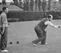
| There was a recreation ground, which included two
bowling greens, for the bowls club and six tennis courts, four with
grass and two hard courts, for the tennis club. There was a cricket
club, a girl's hockey club, a darts club, a badminton club, an
indoor athletics club, a football team, a table tennis team and a
billiards team. There was an annual sports day and each year a
Christmas party was held for the employees children. Frequent dances
and concerts were also held.
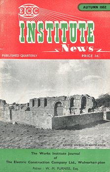
The company also produced a quarterly journal called "Institute
News", which was available for the employees. It contained all
of the latest company news, sports results and a
crossword. There was also an E.C.C. fire brigade, which was
formed in 1903. It was fully equipped and all of the firemen
were trained to deal with any fire that could occur at the
works. |
 |
From a 1910 postcard.
|
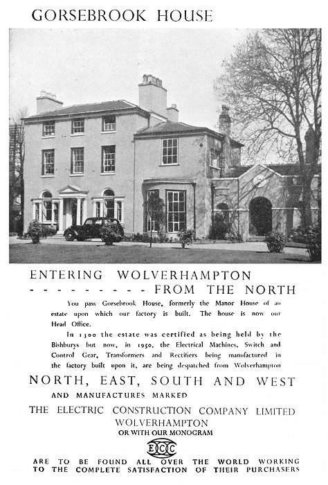
An advert from 1951. |
 |
|

|
|

|
| Return to
the Early Years |
|
Return to
the Beginning |
|
Proceed to
Bushbury Works |
|