| The circuit is extremely interesting as it shows one
of the earliest UK superhets. A separate oscillator is
employed with direct injection into the mixer via the
centre tap on the aerial. Separate plug-in frame aerials
were used for Long Wave and Short Wave (Short Wave is in
fact what we now call Medium Wave). The IF frequency is
260Khz and the gain of the IF amplifier, like on all
early superhets is carefully controlled to eliminate
instability. Early IF transformers were not screened
from each other and valves at this time had a relatively
high internal capacitance. The oscillator and aerial
are tuned separately and so there are two tuning
capacitors. A conventional leaky grid detector is used
and the three audio stages are choke coupled. The final
stage is powered from a 132 volt supply to provide a
loud, undistorted output. The original valves had 6 volt
filaments and were from the "Six-Sixty" range that was
sold by The Electron Company Limited of London. They
are impossible to find these days and so Mullard
equivalents are used instead. |
Circuit
Description
L1 is a plug-in balanced frame aerial that is
tuned by Cl. The output from the oscillator is injected
into the mixer via the aerial's centre tap. The
difference between the oscillator and aerial frequency
is 260Khz, which is of course the I.F. frequency. The
I.F. transformer has an un-tuned primary winding L2,
coupled to tuned secondary circuit L3, C4. |
 |
| Positive feedback is applied to the mixer by C2
(labelled Volume 1 on the front panel) and the centre
tapped aerial coil. This increases the Q of the aerial
tuned circuit, so increasing the gain and the
selectivity. This is an early form of what became known
as a Q multiplier. The oscillator uses a strange
arrangement when compared with more modern techniques.
Anode winding L5 is tuned by C3 and feedback is provided
by L4. Both coils are tapped for Short Wave and the
output is developed across coupling winding L6 and fed
into the mixer. The receiver operates over the following
frequency range:
| Long
Wave: |
150Khz to
346Khz |
|
Short Wave: |
376Khz to
1.192Mhz |
|
 |
The two intermediate frequency (I.F.) amplifiers are
coupled via transformers T1, T2, and T3. Each
transformer has an un-tuned primary winding and a tuned
secondary winding. The transformers are unscreened and
so if the gain was not carefully controlled the
amplifier would be unstable. |
| To prevent instability the amplifier is powered from
just 24 volts and the gain can be adjusted by R1
(labelled Volume 2 on the front panel). |
|
The
detector is a conventional leaky
grid detector, RC coupled from
the secondary of the final I.F.
transformer. C2 filters out any
remaining carrier wave and the
audio signal is developed across
the primary winding of audio
coupling transformer T1.
Audio 2 amplifies the signal
from T1 secondary, and -1.5
volts bias is supplied from the
grid bias battery. The output is
developed across the primary
winding of audio coupling
transformer T2. C3 flattens the
amplifiers' frequency response
by filtering out any unwanted
high frequencies developed
across T2 primary.
Audio 3 amplifies the signal
from T2 secondary and drives the
loudspeaker. Minus 7.5 volts
bias is applied from the grid
bias battery and the loudspeaker
is connected directly to the
PM256 anode and supplied with
132 volts from the HT battery.
C4 filters out some of the high
frequency components giving a
more mellow sound.
The audio
sections of the receiver showing
the two audio coupling
transformers. Courtesy of Graham
James Richardson |
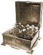
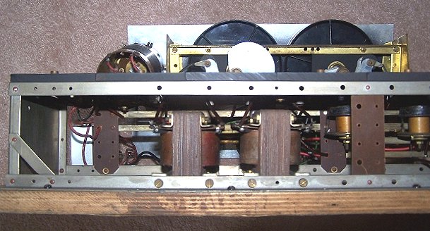
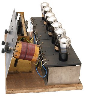
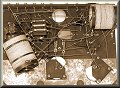
| The construction is very advanced for
the time. The chassis is modular, each receiver
containing the appropriate modules, some of which were
used in several different models. Each module is simply
held in place by two screws. The large coil is the
oscillator coil with the wave change switch inside. It
seems that most of the components including the
switches, tuning capacitors, I.F. transformers and audio
coupling chokes were made in the works. Possibly only
the valves, knobs, and slow-motion drives for tuning
were brought-in.
The valve holders have spring-loaded contacts and
seem to be more reliable than earlier A.J.S. types. |
 |
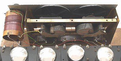 |
A close-up view showing the later type of
A.J.S. tuning capacitor, with the oscillator coil on the
left. The modules are connected to each other via
solder tags that can be seen along the front edge. |
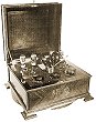
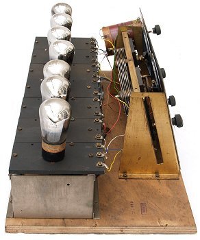
| This view from the left-hand side of the receiver
clearly shows the modules and the way they are connected
together. There is also a row of bus bars that run along
the front edge of the chassis. The chassis varies in
length in different models. This particular receiver is
the most complex model that A.J.S. produced and so the
chassis is quite long. The much simpler two and three
valve radios have fewer modules, as does the 5 valve
superhet.
Modules do not appear to have been used in the
Symphony portable receiver, presumably because of size
and weight. |
 |
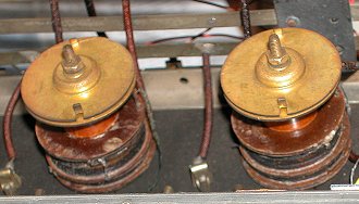 |
A close-up view showing two of the I.F.
transformers. In those days such transformers were not
screened, which seems very strange today. Two of the
bus bars can be seen in the background. |
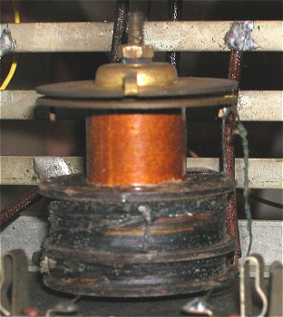
| Another view of an I.F. transformer. The two
windings are at the bottom and the tuning capacitor is
clearly seen at the top. In the bottom right-hand
corner is one of the sprung valve holder contacts. These
appear to work extremely well and are superior to many
of the commercially available valve holders of the day.
Again some of the bus bars can be seen in the
background. |
 |
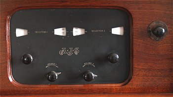 |
The front panel. On the extreme left is the aerial
tuning knob with the oscillator tuning on the right. The
two lower knobs are the gain controls. The knob on the
extreme right is the wavechange switch. |
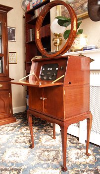
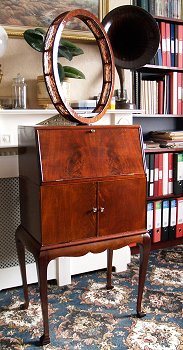
| A front view of the receiver with all of the doors
closed. The batteries are held in the lower compartment.
On the far side of the case is a quarter inch jack
socket for the loudspeaker. The socket includes a pair
of contacts that are wired in series with the
accumulator. They act as the on/off switch. When the
plug is inserted the radio is switched on. |
 |
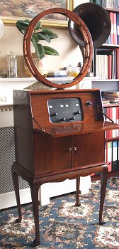 |
Another view of the receiver with the top door open
to reveal the control panel. |
| If anyone has one of these receivers, or any
information about them, or photographs please contact
the webmaster. |
 |
|
|
Return to
the
A.J.S. section |
|
Return to
the
Technical Menu |
|