|
Description
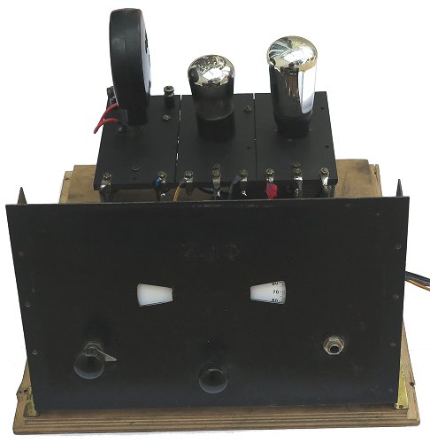
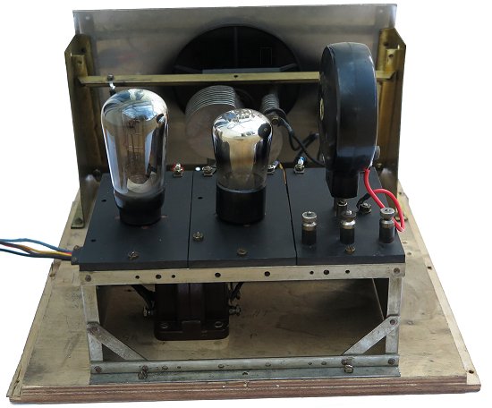
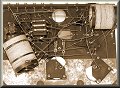
The two-valve receiver is a TRF
design, the first stage consisting of the aerial tuned
circuit, reaction circuitry, a leaky grid detector, and
an audio coupling transformer. The second stage is the
audio output amplifier which drives an external high
impedance loudspeaker, or headphones. Six-Sixty dull
emitter valves are used, along with A.J.S. capacitors
and coils.
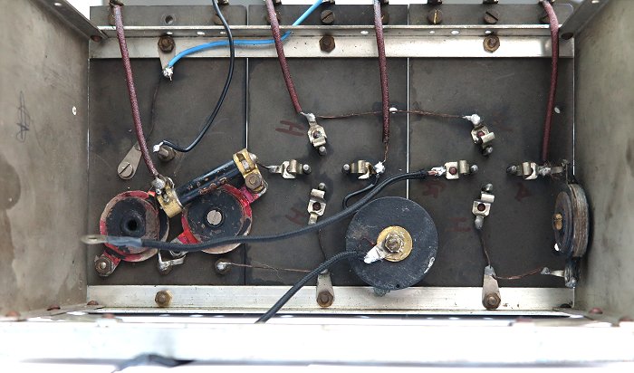
The tuned circuit uses a standard
A.J.S. centre-tapped plug-in coil (L1), which is simply
connected to the aerial by C1 (Aerial 2), or directly
via Aerial 1. As a result the aerial will have a
loading effect on the tuned circuit, altering its
frequency. The tuning capacitor C3 is a standard A.J.S.
component, as is the reaction capacitor C2. The first
stage is a conventional leaky grid detector, biased by
C4 and R1. The centre-tapped aerial coil allows positive
feedback to be applied from the anode via C2.
L2 has two uses. It acts as a radio
frequency loading coil, allowing positive feedback from
output to input via C2 and L1, for reaction, and also
acts as a filter, to filter out the carrier wave and any RF components from the audio output.
The audio output is
transformer-coupled to the audio amplifier V2 which is
biased by the grid bias battery. The output is connected
to a jack socket where an external high impedance
loudspeaker or headphones can be connected. The jack
socket also acts as the on/off switch by switching the
low tension supply. C5 is connected across the output to
flatten the frequency response, compensating for the
inductance of the loudspeaker or headphones. |