The A.J.S. Table
Receiver from 1923 - Inside Out
|
Background
The A.J.S. table model from 1923 uses the company's first
T.R.F. receiver, which has many features that are commonly found
in early British designs. As with most receivers of the day it
has a lot of controls to adjust and easily accessible valves.
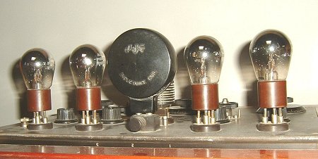
The four valves are bright emitters and so the filament supply
current is very high when compared with later receivers using
dull emitters. As an example, a typical valve of the period, the
L.S.2 has a filament voltage of 6 volts and a current of 1.5
amps, so each filament alone consumes 9watts. The valves have a
relatively short life of several hundred hours, and when new
sold for a few pounds. At the time this was a large sum of money
when compared to the average weekly wage, and so valve radios
were very much a luxury item.
|
|
Each valve filament is fed via a variable
resistor which controls the emission, and so varies the gain of
each stage. It also can extend valve life by running the
filaments at a lower voltage. A valve switch is incorporated so
that fewer stages can be used when receiving strong local
transmissions, or when using headphones. This saves battery
power, and also extends the life of the audio amplifier valves,
by using them less frequently.
The receiver has a tapped aerial
tuning coil for Medium Wave, and a second plug-in aerial tuning coil
for longer wavelengths. The tuned interstage coupling transformer has to be changed for optimum
reception on the longer wavelengths, and as a result it is a plug-in
component. Different versions were available for different
wavebands.
|
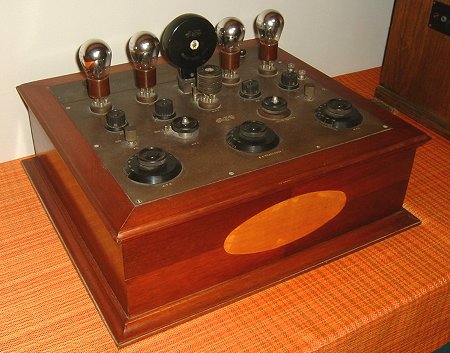
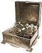
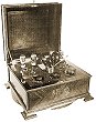
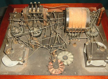
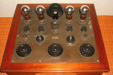
A view of the receiver, a typical
pre-1926 A.J.S. product. The receiver shown in the
photographs can be found at the Olens Radiomuseum in
Belgium. |
|
Components
All of the components except for the
valves, the interstage coupling transformer, the control knobs,
and possibly the screw terminals, and variable resistors, appear
to have been made in-house. Some of them carry A.J.S. patent
numbers. The choke coupled audio stages were always a feature of
any A.J.S. receiver that had more than two valves. |
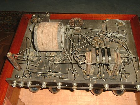
The underside of the top panel.
|
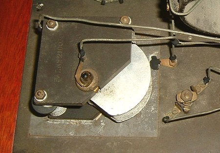
The aerial tuning capacitor. |
The photograph on the left shows the tuning capacitor
for the aerial tuned circuit. It carries the A.J.S. patent
number and was the most common type of tuning capacitor used
by the company. The on/off switch on the right of the
capacitor is a typical A.J.S. switch; examples of
which can be found in all of the company's receivers, other
than the later Symphony range. |
| The reaction coils are very different to the ones used
in later A.J.S. receivers, and are of a much simpler form of
construction. |
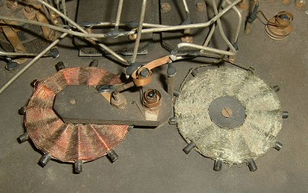
The reaction coils. |
|
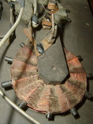
A close-up view of one of the reaction
coils. |
The photograph on the left shows the moving reaction
coil. It is mounted on the end of
a short arm that is attached to the reaction control shaft.
When the shaft rotates the two coils are brought closer
together so that feedback will occur. A contact is mounted
on the arm to short circuit the coil when reaction is set to
minimum. |
| The photograph shows the audio coupling chokes that were
used in all A.J.S. receivers with more than two valves. |
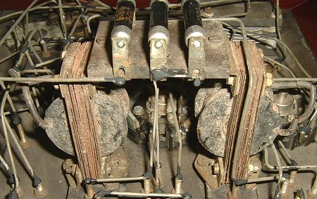
The audio coupling chokes. |
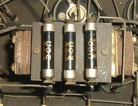
A.J.S. carbon resistors.
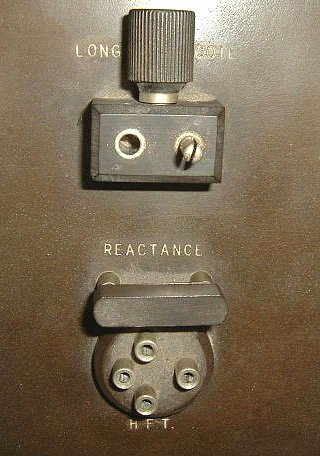 |
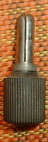
A close-up view of the sockets for
the plug-in coils. The upper
socket for the Long Wave coil contains the plug on the
right, which when inserted short circuits the plug-in coil.
It acts as a Long Wave/Medium Wave switch and also allows
the receiver to function when the coil is not inserted.
The lower socket is for the plug-in
Neutrodyne H.F. coupling transformer. Different coils were
available for different wavebands.
Above the socket is a plug-in link
labelled reactance. The reaction control and built-in
reaction coils are for Medium Wave only. Presumably a
plug-in coil was available for Long Wave reaction. |
 |
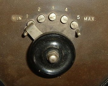 |
The coarse aerial tuning
switch. This early type of switch was not used in any of
the later A.J.S. designs. |
|
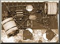
A final view of
the internal circuitry.
|
 |
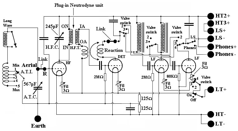
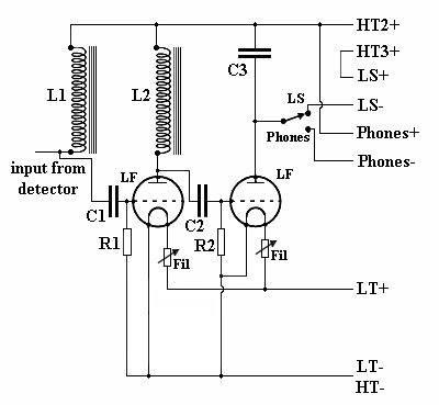
The circuit diagram.
| The receiver is a 4 valve T.R.F. design with a tuned
high frequency amplifier, a detector, and a two-stage audio
amplifier. It covers part of the Medium Waveband and Long
Wave, or other wavebands using suitable plug-in coils. The
two audio stages can be switched in, or out, as required to
reduce battery consumption. |
|
Circuit Description
High Frequency Amplifier |
|
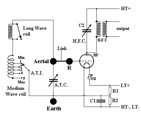
A simplified version of the high frequency
amplifier. |
The aerial tuned circuit consists of
the tapped Medium Wave coil, the plug-in Long Wave coil, and aerial
tuning capacitor A.T.C. The Long Wave coil socket contains a
shorting plug to short circuit the coil when the receiver is used on
Medium Wave, or when the Long Wave coil is not inserted in the
socket. There is an external link between the aerial terminal and
the 'R' terminal so that an A.J.S. Patent Rejector Circuit can be
used with the receiver to remove unwanted signals.
The taps on the Medium Wave coil and the A.T.I.
switch provide coarse tuning. No attempt is made to match the aerial
into the tuned circuit, which must have been severely damped, or
detuned by the long wire aerials in use at the time.
The output at the valve anode is tuned by C2
and the interstage coupling transformer. This plugs-in to allow
other transformers to be used for different wavebands.
|
|
The valve is biased by potential divider R1 and
R2 across the low tension supply. The bias voltage is decoupled by
C1.
The variable resistor in series with the
valve filament allows the gain of the amplifier to be adjusted. As no
attempt is made to neutralise the valve's internal capacitance, it's
likely that the amplifier could be unstable at certain frequencies.
This would depend upon the type of aerial used and the setting of
the variable resistor. |
|
The detector is a conventional leaky grid
detector, directly RC coupled from the interstage coupling
transformer H.F.T. The valve is biased by the leaky grid
coupling components C2 and R3, and the potential divider across
the low tension supply, R1 and R2, which is decoupled by
capacitor C. The positive voltage from R1
and R2 biases the valve to improve the linearity of the detector
to minimise audio distortion and provide a high quality output. The remaining carrier wave
at the output is filtered out by C3.
The variable resistor in series with
the valve filament will alter the gain of the detector and also
its characteristic. A high gain might be useful when
receiving weak signals.
Medium Wave reaction is provided by the
two ‘basket wound’ coils, L1 and L2. The reaction control
moves the coils closer together to increase positive
feedback until oscillation occurs. It also includes a pair
of contacts to short circuit L2 at minimum reaction, so that
no feedback will then occur.
There is a plug-in link on the panel next
to the Long Wave coil. This allows an external reaction coil to
be plugged-in for Long Wave operation. It will provide positive
feedback to the input of the high frequency amplifier via the
Long Wave aerial coil. |
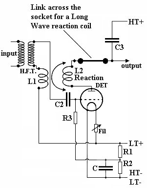
A simplified version of the detector. |
| The output is connected to the valve switch so that it
can be directly connected to a pair of headphones in two
valve operation, or be connected to the first audio coupling
choke when the audio amplifier is in use. Audio Amplifier |
|
The audio amplifier without the valve
switch. |
The first audio amplifier is choke coupled from the detector by
L1, C1 and R1. Similarly the audio output stage is choke
coupled to the first audio amplifier by L2, C2, and R2. C3
which is in parallel with the loudspeaker or headphones
helps to maintain a constant anode load at all audio
frequencies. This is because the high impedance loudspeakers
and headphones are predominantly inductive and so their
impedance is more or less directly proportional to
frequency.
The variable resistor in series with each valve filament
varies the gain of each stage and can also be used to reduce
the current drain from the low tension accumulator. The loudspeaker
positive terminal is directly connected to the HT3+ terminal on the
back panel, so that the audio output can, if necessary, be supplied from a
higher voltage to provide a higher audio output. |
|
Another view of the receiver.
A final view of the receiver. |
|
All of the photographs were kindly supplied
by Joris Van Campenhout of the Olens Radiomuseum in Belgium. We
thank him for all of his help in producing this section.
We would like to add technical details of
other A.J.S. receivers, if anyone can help please email the
webmaster.
|
|
Return to the
A.J.S. section |
Return to the
Technical Menu |
|
|