The A.J.S. Type 'E'
Receiver - Inside Out
|
Background
The A.J.S. type ‘E’ receiver used what became the company’s
standard T.R.F. design that was used in most of the A.J.S. non-superhet
receivers. The same components are used in many of the two and
four valve sloping panel models, the more expensive table
models, the pedestal receivers and the top of the range Console
model. The type "E" first appeared in 1924 complete with a
built-in H.T. voltmeter. In 1925 the voltmeter was removed and
an instruction panel added to cover the hole where the voltmeter
used to be.
|
|
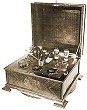
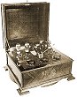
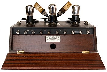
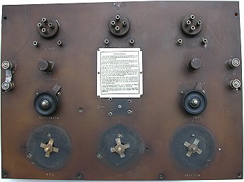
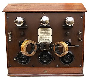
The sloping panel type 'E' receiver with the
top open. |
|
Components
Most of the components were made by the company. A.J.S.
produced all of the coils including the tuning coils, reaction
coil and the audio coupling coil. The company also made most of
the components including fixed capacitors, variable capacitors,
multi-pole rotary switches, resistors and valveholders, in fact
almost everything. Knobs were almost certainly brought-in and it
is uncertain as to whether the laminations for the audio chokes
were made in-house.
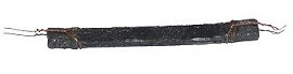
The inside of an A.J.S. carbon resistor.
The carbon resistor appears to
be a piece of carbonised card that has been dipped in wax.
|
| The valves used in A.J.S. receivers were initially made by
Mullard and carried the company’s logo. When A.J.S. started
receiver production in 1923, valves used plain tungsten
filaments which had to be heated to around 2,000 degrees
centigrade to obtain adequate emission. These were
understandably called ‘Bright Emitters’ and required high
filament currents and had a relatively short life. These valves
were very expensive and it was common for suppliers to offer a
service to replace a burnt-out filament. |

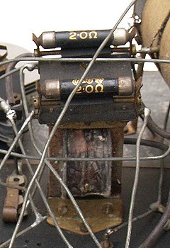
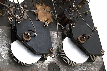
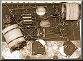
The bottom view of the receiver. |
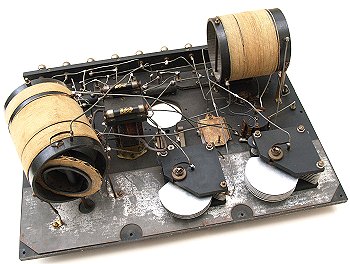
| Another view of the
underside showing the reaction coil on the left. |
|
Around 1925 this all changed with the development of ‘Dull
Emitters’. These use a filament that is coated with Barium or
Strontium oxide and gives a much higher electron emission than
plain tungsten. The filaments now only have to be heated to
around 800 degrees and only emit a dull glow, hence the name.
The filament current is greatly reduced and the valves last a
lot longer. This receiver would have used Mullard dull emitters
from the PM series consisting of the following:
| HF - |
PM1HF |
| DET - |
PM1LF |
| LF - |
PM2 |
|
| A.J.S. accumulators were made by Joseph Lucas Ltd.,
and the high tension batteries were made by Ever Ready, Columbia and
Siemens. |
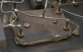
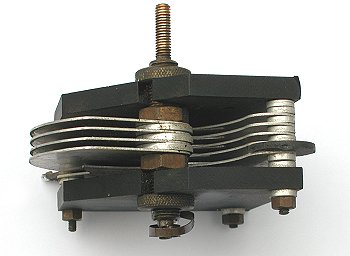
| A close-up view of an A.J.S. tuning
capacitor, patent number: 210030
and 209986 |
 |
 |
This view of a tuning capacitor
shows the flexible brass strip at the top of the shaft to
connect the moving vanes to the solder terminal. The brass
strip also acts as a light spring and so when the capacitor
is fully closed it will tend to open again. To eliminate
this a thin spring washer is fixed under the shaft mounting
nut to apply a small amount of friction to the shaft so that
it can't move too freely. The nut is adjustable to set the
pressure. |
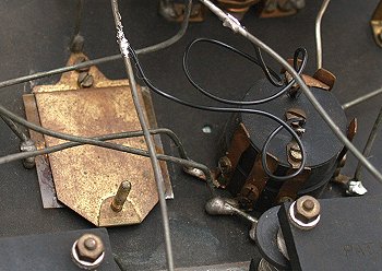
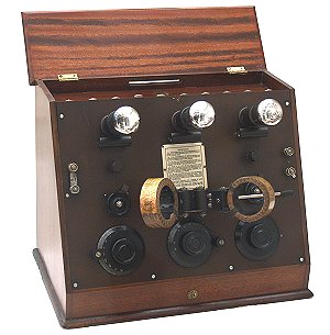
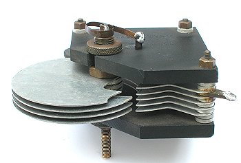
| This view shows both of the tuning
capacitors in the receiver, aerial tuning on the right and
high frequency tuning on the left. The metal plate in front
of them eliminates hand capacitance effects. |
 |
 |
An unrestored receiver minus long
wave coils, valves, tuning and reaction knobs. The thin
spring washers that apply a small amount of friction to the
tuning control shafts can be seen under each central nut. |
|
The circuit diagram of an A.J.S. type 'E'. |
| The type ‘E’ receiver is a three valve T.R.F.
design consisting of a tuned high frequency amplifier, a detector
and an audio amplifier. It covers three wavebands; short wave
(higher end of the medium wave band), broadcast (lower end of the
medium wave band) and long wave (with the external coils). |
| A vario-coupled reaction circuit is used which prevents
external radiation on the short wave and broadcast bands and
a metal screen is incorporated to eliminate hand capacitance
effects. Provision is made for switching-out the last
valve, so that the receiver can operate as a two or three
valve radio to reduce battery consumption. In the 1920s high
tension batteries were very expensive and the accumulators
usually had to be taken to a local shop for charging, so
this kind of facility would appeal to purchasers. Each valve
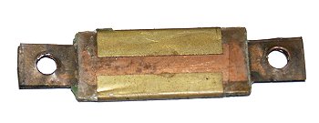
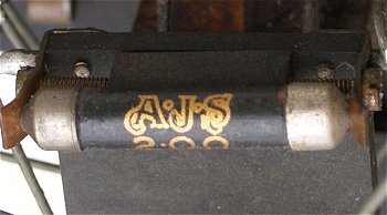
is fitted with a
3.2Ω plug-in resistor in series with the
filament that can be changed to allow a wide range of valves
with different filament voltages to be used. A range of
suitable plug-in resistors was available from A.J.S.
dealers. |
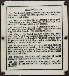
The instruction panel. |
|
Circuit Description
High Frequency Amplifier |
A simplified version of the high frequency
amplifier showing just the short wave and broadcast band components. |
Broadcast and Short wave bands
The aerial tuned circuit consists of L1 and C1, L1 being tapped
for short wave. La is the aerial coupling coil which acts as a
coupling capacitor (one end is not connected).
The output of the amplifier is tuned by L4 and
C2. L4 is tapped for short wave and is mounted at right angles to L1
to prevent feedback. The internal capacitance of the valve could
produce instability and this is eliminated by neutralising circuit
L5 and C3. The negative feedback from L5 is adjusted by neutralising
capacitor C3 to counteract any positive feedback resulting
from the valve’s internal capacitance.
|
| Two terminals on the front panel, normally linked,
allow for the connection of an external tuning coil and two
terminals on the top panel (labelled R and R and normally linked) in
series with V1 grid, allow an A.J.S. Patent Rejector Circuit to be
used with the receiver. |
Long wave band
External plug-in aerial and anode tuned circuits are used on
long wave. Aerial coil L2 and output coil L3 plug into a switched
socket on the front panel. When the coils are removed their
connections on the socket are automatically short-circuited. In use
long wave is selected on the rotary wavelength switch and the coil
arm is raised. If the arm is fully lowered the coils are
switched-out. The arm controls the coupling between the coils. They
are connected so that positive feedback will result if the coils are
closely coupled and so the arm acts as the long wave reaction
control. L4, L5 and C3 remain in circuit on long wave to provide
neutralisation and the aerial is directly connected to the aerial
tuned circuit.
|
A simplified version of the high frequency
amplifier showing just the long wave components. |
| A range of plug-in coils was available allowing
the receiver to operate down to 55KHz. |
|
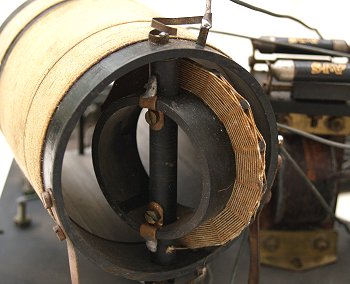
The detector.
|
Detector
The detector is a conventional leaky grid
detector, directly RC coupled from V1 anode. L6 is mounted
inside L4 and is rotated by the reaction control knob to alter
the amount of coupling between the two coils. This provides
positive feedback for reaction. L6 is a very thin coil so that
the coupling between the coils at zero reaction can be reduced
to an extremely low value. It also provides an extremely fine
and precise reaction adjustment.
This type of coil used to be described as
‘basket wound’ and sometimes called a basket coil. On the short
wave and broadcast bands this is the only reaction control, but
on long wave the main reaction is adjusted by the coil arm and
the reaction knob becomes a fine reaction control. C4 filters
out any remaining carrier wave and the audio signal is developed
across audio coupling choke L7.
|
|
Audio Amplifier
The audio amplifier is RC coupled from the detector by C6
and R2. The output is connected to a moving iron horn
loudspeaker or headphones via the selector switch.
|
Audio Output. |
|
A final view of the receiver. |
|
We would like to add technical details of
other A.J.S. receivers, if anyone can help please email the
webmaster.
|
|
Return to the
A.J.S. section |
Return to the
Technical Menu |
|
|