The A.J.S. Type 'Z' Receiver - Inside Out

 
Background

A.J.S. receivers were always aimed at the top end of the market. They were very expensive, and unaffordable to many. Having said that, most valve radio receivers were expensive at the time, which is why crystal sets were so popular. In 1925 when the Type ‘Z’ was launched, the Radio Electric Company in Wolverhampton was selling crystal sets for as little as seven shillings and sixpence.

The Type ‘Z’ sold for £8.2s.6d. which in modern money (based on the retail price index) equates to £361.00. At the time wages were very low, and so based on average earnings, the receiver today would cost a staggering £1,210.00. It was also available with all the required accessories at a selling price of £13.18s.6d. The complete kit consisted of a Type 'Z' receiver, an A.J.S. Junior loudspeaker, an accumulator, two 50 volt H.T. batteries, a set of A.J.S. coils, connecting wire, 100 feet of aerial wire, two shell insulators, and a 9 inch lead-in tube for the aerial wire.

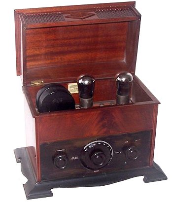
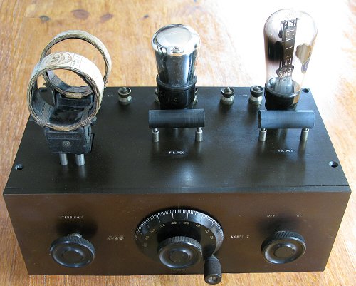
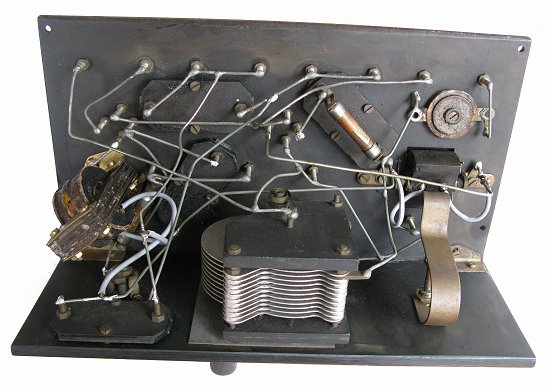
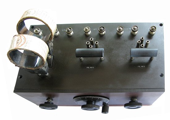
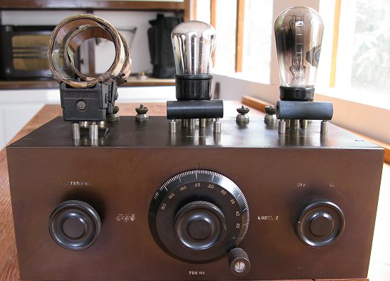
The type ‘Z’ was the company’s cheapest and simplest design, consisting of a 2 valve T.R.F. receiver. The first stage, a leaky grid detector with reaction, is choke-coupled to an audio amplifier. It was designed for use with a loudspeaker when listening to strong signals, such as local BBC broadcasts, or with headphones when listening to more 
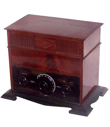
distant stations. The ornate cabinet is built to the same high standards as the cabinets used in the company’s more expensive receivers.


The A.J.S. Type 'Z'.

Circuit Description

The receiver uses standard plug-in coils for tuning and reaction (L1 and L2), and Mullard dull emitter valves. All of the capacitors and the audio coupling choke are made by A.J.S.

Because the tuned circuit uses a standard plug-in coil (L1), the aerial is simply connected to the circuit by C2, and so will have a loading effect on the circuit. The tuning capacitor C1 is a standard A.J.S. product. The first stage is a conventional leaky grid detector, biased by C4 and R1. The plug-in filament resistor R2 can be changed when valves with a different filament voltage are used.

Reaction is provided by positive feedback from plug-in coil L2 which is mounted on a swinging arm that brings L2 closer to L1 so that feedback will occur. The audio signal at the detector anode is developed across audio coupling choke L3. Any remaining carrier wave is removed by C3. Because of the damping effect from the aerial, the amount of positive feedback between L1 and L2 depends upon the type of aerial in use.

The audio signal is ac coupled into the audio amplifier by C6, and developed across grid resistor R3. As in the first stage there is a plug-in filament resistor (R4) which can be changed when valves with a different filament voltage are used. The audio output signal at the anode can be fed to a high impedance loudspeaker, or headphones. The high tension supply is decoupled by C5.

The underside of the receiver showing the simple and quick construction techniques that were used.
This view shows the simple reaction mechanism. The 'U' shaped spring-loaded arm is opened or closed by the reaction control shaft, which is screwed in-or out by turning the reaction knob.

On the bottom of the pivoted reaction coil holder is a pin that goes through a hole in the spring loaded arm. As the arm moves it alters the distance between the coils.

A view showing the audio coupling choke that was greatly favoured by A.J.S.

The tuning capacitor is a standard A.J.S. product.

A view from above which shows the plug-in filament resistors, and the standard A.J.S. valve sockets.
Another view from above.


A final view of the receiver.

I would like to add technical details of other A.J.S. receivers. If anyone has any information please email the webmaster.


Return to the
A.J.S. section
  Return to the
Technical Menu