Transmitters
At this time transmitters were of the spark-gap type and were used to
transmit morse code. A transmitter consisted of an induction coil, a
morse key and a battery. When the key was closed a current flowed into
the induction coil. The coil acted as both a solenoid and step-up
transformer. A pair of contacts was in series with the coil and was used
to interrupt the direct current so providing a series of pulses for the
transformer. When current was applied to the coil, the iron core was
magnetised, and the magnetic field attracted a metal bar that was
attached to one of the contacts. This turned off the supply current and
caused the magnetic field to collapse, so returning the contact to its
original position. The circuit was made again and the whole process
repeated indefinitely until the key was released. Each time the contacts
opened, the rapidly collapsing magnetic field induced several thousand
volts in the secondary winding.
A parallel tuned circuit and a pair of spark gaps were connected
across the secondary winding. The high voltage pulses charged the
capacitor, and when the voltage was high enough, the air in between the
spark gaps (two metal balls) was ionised and a visible spark would jump
between them. This caused a current to flow in the tuned circuit, which
produced a damped oscillation. While the key was pressed there was a
continuous train of sparks and so the voltage across the tuned circuit
consisted of a series of damped oscillations at the resonant frequency
of the tuned circuit. Suitable values of capacitor and coil were used to
determine the transmission frequency. With the addition of an aerial and
earth the resulting signal could be sent over long distances.
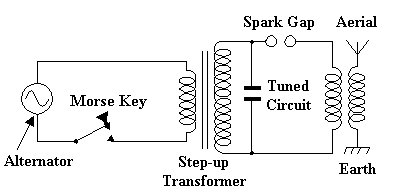
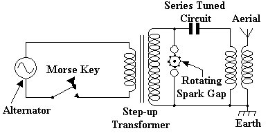
A typical Marconi spark gap transmitter
with A.C. source and step-up transformer. |
Marconi also designed transmitters that replaced
the battery and induction coil with a low voltage alternating
current source, and a step-up transformer. The alternating
current was supplied by an alternator. The morse key was
connected in series with the alternator and the primary winding
of the transformer. |
The output from the transformer secondary winding was in the range of
2,000 to 25,000 volts. The aerial was coupled to the tuned circuit by a
small impedance-matching coupling coil.
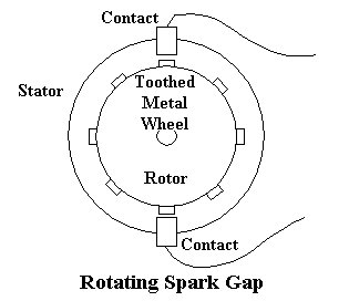
| Rotating spark gaps were also employed. They
produced a more regular spark and could handle more power than a
conventional spark gap. The inner rotating metal disc had a
number of teeth on its outer edge. A discharge takes place when
two of the teeth are in line with the two outer contacts which
carry the high voltage. The speed of the rotor is adjusted so
that the contacts are in line on the positive and negative peaks
of the incoming A.C. voltage. This produces a discharge on each
half cycle which gives rise to a damped oscillation in the tuned
circuit. |
 |
|
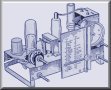
A 0.5KW ship's transmitter with rotating
spark gaps. |
Rotating spark gaps were used with an A.C. source
and step-up transformer. This circuit is of a ship's transmitter
which was driven from a motor generator that was powered from
the ship's electricity supply. The output power was half a
kilowatt and the range was between 500 and 700 miles. |
| The output waveform from a typical rotating spark
gap transmitter consists of a series of damped oscillations.
This waveform is much more regular and cleaner than that
obtained from a transmitter using an induction coil. It is still
not good enough however, for speech which requires a clean
carrier wave, rather than a series of damped oscillations. |
 |
Speech was first transmitted in 1906 by R.A. Fessenden, who was a
Canadian engineer working in America. He transmitted speech and music
from Brant Rock, Massachusetts, using a special high frequency
alternator, which generated an 800KHz sine wave. People who tuned in to
these transmissions were amazed to hear voices from their headphones.
Although the technique worked, it was far from practicable. A high
current flowed through the microphone which caused it to run at a very
high temperature. The transmission of speech and music wasn't really a
practical proposition until reliable thermionic valves were available.
Receivers
|
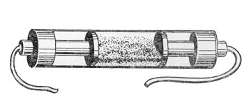
An early coherer. |
Early receivers used coherers to detect radio
waves. A coherer consisted of a glass tube containing metal
filings. When a high frequency current passed through the
filings they tended to stick together, so reducing their
electrical resistance. When the filings had stuck together the
tube had to be tapped to separate them again. This was very
impracticable, and soon became obsolete. |
Until valves were available the most common type of receiver was the
crystal set. It was extremely simple but was not very sensitive or
selective.
| Many of these receivers used the 'cat's whisker'
type of crystal diode for detection of a radio signal. The diode
allowed current to pass in one direction but not the other, and
so rectified the received carrier signal to provide a D.C.
voltage that could drive headphones. |
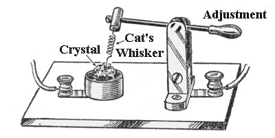
A typical cat's whisker. |
Several minerals were used for the crystal, including zincite,
silicon, galena, molybdenite, bornite and tellerium. Rectification takes
place at the point of contact with a sharp metal point such as the end
of a phosphor bronze wire. A precise contact had to be made for the
device to operate. The device was extremely unstable and much time could
be spent in adjusting the wire to get a suitable contact. The cats
whisker was basically a small spring that held the point in contact with
the crystal.
|
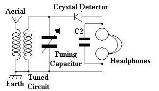
A simple crystal set. |
The signal from the aerial was inductively coupled
into the tuned circuit, which was adjusted by the tuning
capacitor. The signal was rectified by the crystal diode and fed
to the headphones. The capacitor across the headphones charged
to the peak value of the signal from the diode, and so filtered
out the carrier signal, to leave just the modulation, which
corresponded to the morse dots and dashes. |
| A more reliable detector was the carborundum
rectifier. Unlike the cat's whisker it was stable, but required
a negative potential of 1volt to be applied, for it to operate
at its most sensitive point. This was supplied by the batteries
and adjusted with the potentiometer. |
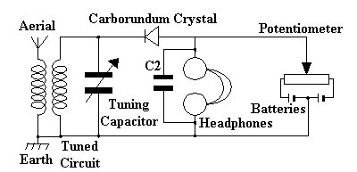
A simple crystal set using a carborundum
crystal. |
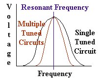 |
The above receivers were extremely unselective, so
that transmitters on adjacent frequencies often caused
interference.
This could be improved by using more than one
tuned circuit to sharpen up the frequency passband. The wide
outer curve in the diagram is from a single tuned circuit,
whereas the narrower inner curve is from several circuits. |
The circuit above shows a more selective version of the carborundum
crystal receiver. The improved selectivity is obtained from the extra
two tuned circuits, which are inductively coupled. The only problem with
this receiver is that there are now three tuning adjustments.
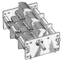
| This was overcome by operating the three
capacitors from a single shaft, such as in the opposite
diagram.
The capacitor in the diagram however, is a more modern
type than would have actually been used in a crystal receiver. |
 |
Return to
the History
of Radio |
|
|