|
|
|
|
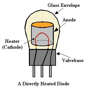
The Diode The thermionic valve, as the name suggests, is a device that controls the flow of something. In this case its a stream of electrons in a vacuum.
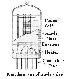
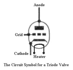
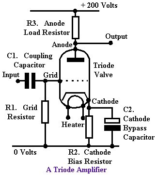
The Triode The triode or three electrode valve, is a diode with the addition of a spiral wire in between the cathode and anode. This is called the control grid, and when a negative voltage is applied to it, the flow of electrons between the anode and cathode is reduced. As the negative voltage on the control grid is increased, the electron flow will be reduced even more, so allowing the current flow through the valve to be controlled.
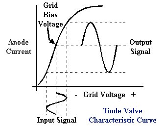
If the supply voltage to the anode is fairly high and is connected via a large resistor, a large voltage will be developed across the resistor, due to the current flowing through the valve. If a small negative voltage is applied to the control grid, it will reduce the current flowing through the valve. This will increase the anode voltage, and a smaller voltage will be developed across the resistor, which is called the anode load resistor. The small control grid voltage will have made a large change to the anode voltage, so the valve has amplified this voltage.
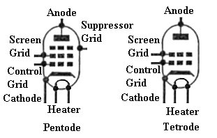
Other types of valve include the tetrode which has a second grid inserted in between the control grid and anode. The second grid is called the screen grid and improves the high frequency operation of the valve, and increases the amount of amplification. It has a positive voltage applied to it.
Variable-mu Valve If the wires in the control grid are spaced closer together at the centre, the grid bias voltage will vary the valve's gain. This is often used in radio receivers to allow them to handle very strong and very weak signals. T.R.F. Receivers Many of the early valve receivers were of the tuned radio frequency type or TRF for short. These consisted of a number of valve amplifiers, which were each tuned to the incoming radio frequency, a detector and audio amplifier. Often the tuned stages, as in the circuit diagram below, were individually tuned, so there were several adjustments to make when tuning the radio to a station.
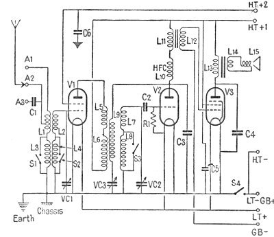
Circuit Description The aerial is connected into the receiver via one of the aerial sockets; A1, A2 or A3. These are provided to give the best results from a variety of aerials and signal strengths. This is a Medium and Long Wave receiver, and the waveband is selected by S1, S2 and S3. The aerial tuned circuit consists of tuning capacitor VC1, and either medium wave coil L2, or Long wave coil L4. V1 is a tetrode amplifier that amplifies the tuned signal from the aerial. The output from the amplifier is coupled to V2; the detector, and audio amplifer, by L5, L6 and tuned circuit VC2, L7 and L8. L9 feeds the signal from the output of V2, back to its input and so the circuit can turn into an oscillator. The amount of feedback is controlled by VC3 which is the reaction control. In use the reaction control is adjusted so that the receiver can operate just below the point where oscillation starts. This gives the maximum gain and selectivity. On a strong signal the control can be set to give the minimum gain. In fact in this receiver the reaction control provides the only control of volume.
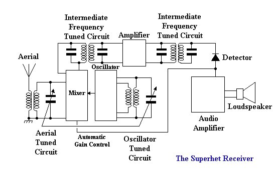
H.F.C. (high frequency choke) L10 is used as a load for the reaction part of the circuit, and the audio signal is coupled to V3 via transformer L11 and L12. V3 is the main audio amplifier, which drives the loudspeaker via transformer L13 and L14. Grid bias is provided by the grid bias battery, the heaters are powered by the LT battery, and the radio is powered by the HT battery, which provides two voltages at HT +1 and HT +2. S4 is the On-Off switch. The circuit is typical of an early TRF receiver from the mid 1920's, to the early 1930's. The Superhet A superhet receiver is more complex than a TRF receiver but has many advantages. Its tuning is much simpler and its much more selective, so it’s a simple matter to tune in to a station and not hear adjacent stations in the background. Superhets are more sensitive than their TRF counterparts, as its an easier matter to amplify the radio signal before detection.
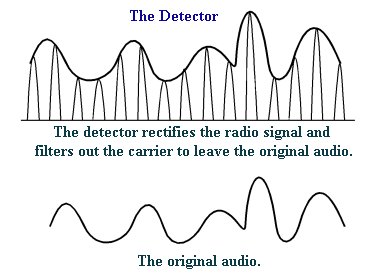
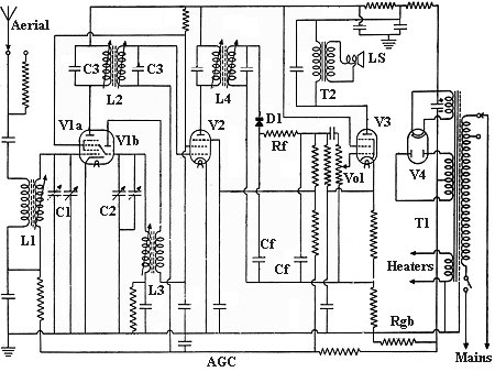
A superhet uses a mixer, or frequency changer as its also called, to convert any aerial signal to a fixed frequency. This is done by mixing the aerial signal with the signal from an oscillator. When the two are combined in the mixer, it produces the original signals plus their sum and difference frequencies. When a station is tuned in, the oscillator frequency is also adjusted so that the difference in frequency between it and the tuned frequency is always the same. This gives a constant difference frequency which can be easily amplified, and by using suitable tuned circuits its bandwidth can be precisely set so that the receiver is very selective. The difference frequency is called the intermediate frequency, or I.F. frequency for short. After amplification the I.F. goes to the detector to obtain the original speech or music. The detector also provides a negative voltage that is used to control the overall gain of the receiver. It is called the 'automatic gain control' or AGC for short. The stronger the signal, the greater the voltage will be, and so the gain will be reduced accordingly. This is done by using a variable-mu valve in the mixer. The audio output from the detector goes to the volume control, and to the loudspeaker via the audio amplifier. This type of receiver first appeared in the mid 1920’s and is what we still use today. Circuit Diagram
The signal from the aerial is tuned by L1 and C1. V1a is the mixer, its output is tuned to the I.F. frequency by L2 and C3. V1b is the oscillator, which is tuned by L3 and C2. V2 is the I.F. amplifier which produces most of the receiver's gain. Its output is tuned by L4 and the two associated capacitors. D1 is the detector diode, and Rf and Cf forms the filter that removes the radio frequency carrier from the detected audio. D1 also provides the negative voltage for the receiver's AGC which goes to V1a and V2. The audio signal from the detector goes to the volume control (Vol) and audio amplifier V3. The loudspeaker (LS) is driven by the audio amplifier via the output transformer T2. The mains power supply consists of mains transformer T1 and rectifier V4. The transformer has a secondary winding to supply an A.C. voltage to the heaters of the valves, which are indirectly heated, and a separate heater winding for the rectifier, V4. The third winding provides the A.C. voltage for the rectifier which supplies the receiver HT voltage. Grid bias for V1a and V2 is provided by the voltage that is developed across resistor Rgb, through which the HT current flows. The descriptions in this section have been limited by space. It would require a lot of basic theory to be explained before anyone who is totally unfamiliar with electronics, could thoroughly understand the operation of the circuits. The information is provided here as a background to the products that are described, as its impossible to avoid some technical words in the descriptions. It also helps to put to developments in the industry into context.
|