| The photographs below show just a few of the vast
number of products that were made by the company. Their
range of diesel engines, hydraulic and pneumatic
products was very large. I hope the few images that are
included below will give an idea of Turner's engineering
expertise. |
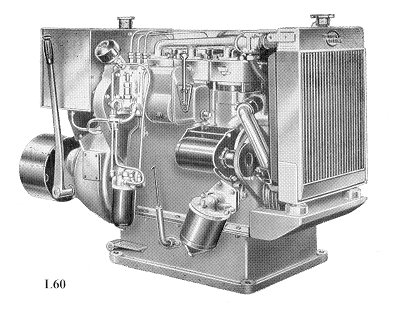 |
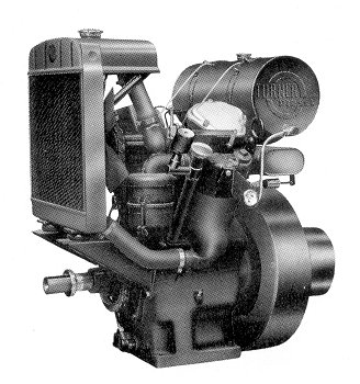
A Turner 2 stroke,
supercharged, industrial diesel engine type L60. |
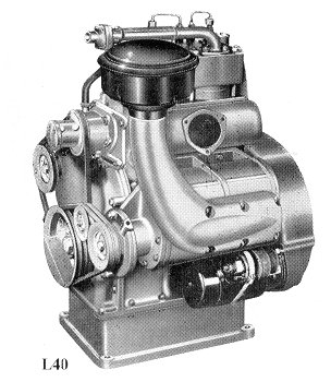
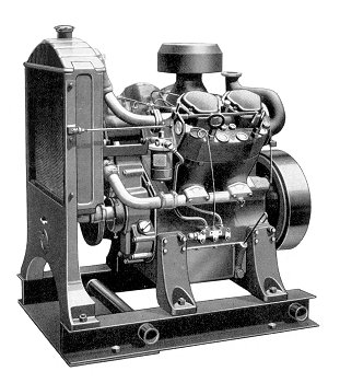
A Turner 2 stroke,
supercharged, industrial diesel engine type L40.
Suitable for generator sets, compressor
sets, pumping sets, welding equipment, power packs, and
winches etc. |
 |
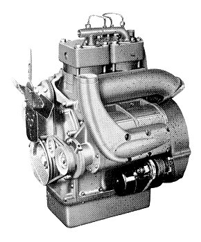 |
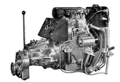
A Turner 2 stroke, automotive
diesel engine type L40.
It was designed for use in light and medium weight
commercial and passenger vehicles such as Land Rovers,
industrial taxis, agricultural tractors and harvesting
machines etc.
|
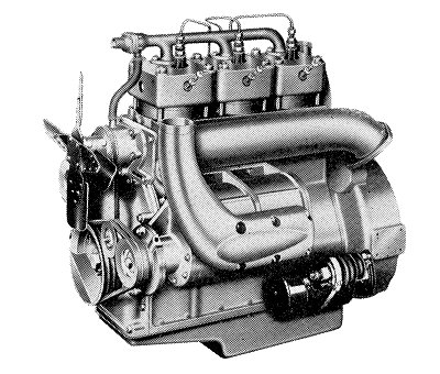
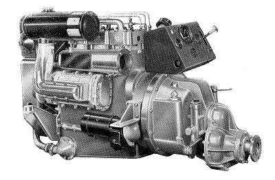
| A Turner 2 stroke, automotive
diesel engine type L60.
It developed 56b.h.p. at 2,800r.p.m., and had a maximum
speed of 3,150r.p.m. It could deliver a maximum torque
of 15.78 M.Kg. |
 |
 |
A Turner 4V95 four cylinder,
30 to 36hp. It was developed for the 'Yeoman of England'
agricultural tractor but was also available in a variety
of forms. |
| The smaller Turner
2V95 which like its bigger brother was available in a
number of forms. Tank
cooling or radiator cooling versions were available as
was a radiator cooled version with a clutch. |
 |
 |
A Turner 'Sea Princess' 2
stroke, supercharged marine unit.
They were the lightest marine
units in their power class in the world. |
The larger Turner 'Sea Prince'
2 stroke, supercharged marine unit. |
 |
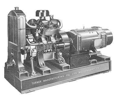 |
Turner also produced diesel
generator sets.
The one opposite could produce
18.5kW,(23kVA). They were available as 3 phase or single
phase units.
The 3 phase units supplied
either 400 volts or 230 volts and the single phase unit
supplied 110volts. |
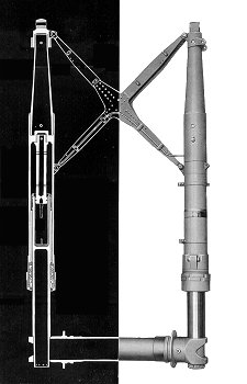 |
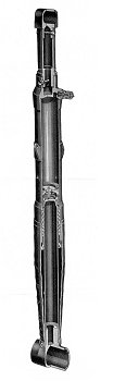
Turner pneumatic aircraft
undercarriages. The units
were both light and extremely simple, and were used on
many well-known aircraft.
Energy was absorbed during both
compression and extension of the shock absorber by the
passage of air through the throttling holes. |
 |
| Turner also produced a wide
range of rotary oil pumps for use in hydraulic systems.
They were used in many applications such as machine
tools, and jacks, or any system that required hydraulic
power. |
 |
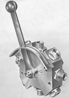 |
The photograph opposite shows
a Turner selector valve for use with their hydraulic
systems. This particular example has four ports.
Hydraulic equipment was very important to the company,
and large numbers of systems and components were
produced. |
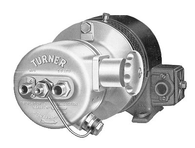
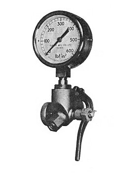
| Turners also manufactured test
equipment for hydraulic systems. The photograph opposite
shows a 772B MK2 Inflation Adaptor, which is a pressure
gauge for attaching to a hydraulic system. |
 |
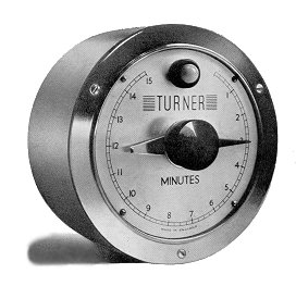 |
The company also manufactured
interval timers for use in any application where
accurate timing was required. |
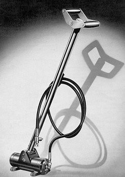
| The photograph opposite shows
a Turner air pump which was used for the inflation of
pneumatic aircraft undercarriages. It is one of the many
air pumps that were produced by the company. |
 |
An advert from 1956.
| The following article appeared in 'The Engineer', on
13th December, 1946: |
|
An Air-Operated Hydraulic Pressure Testing Pump
A compact small pump, designed
for use with high pressure hydraulic testing
equipment which is now being made by the Turner
Manufacturing Company, Limited, Villiers Street,
Wolverhampton, is illustrated in the accompanying
engraving. It is designed for coupling directly to
existing factory air lines, and serves as an
intensifier which uses the pressure of the air to
raise the oil or water in the hydraulic system to a
higher pressure. |
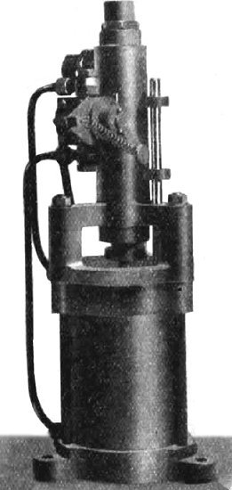 |
The pump has two cylinders arranged vertically
in tandem, the pistons in each cylinder being
coupled together by a common connecting rod. The
piston in the lower cylinder is actuated by the
compressed air and it has a considerably larger
surface area than the upper piston.
Air is supplied to the double acting lower
cylinder through a ported rotary valve, which is to
be seen on the side of the upper cylinder in the
illustration. This valve is operated through a push
rod connected to the air piston and projecting
upwards through the cylinder cover. The air valve
spindle is balanced by a spring and is unaffected by
the air pressure. This arrangement avoids any
tendency it might have to stick when being swung
over.
In order to save time when filling the hydraulic
system, the hydraulic inlet and outlet valves have
been designed to lift at relatively low pressures so
that liquid from the mains supply can flow straight
through the pump.
Once the pressure in the system equals that of
the mains supply, the pump begins forcing the
pressure up to the required figure. The pump
operates continuously until the maximum pressure is
reached when it stops automatically. |
|
It holds the pressure
indefinitely without any loss, but if the hydraulic
pressure is lowered during the test the pump
restarts automatically. An air-reducing valve which
can be fitted to the unit permits an infinite
variation of air pressure up to the maximum of the
mains supply.
Pumps are made in two types,
each working with an air supply of 80 lb per square
inch. One pump delivers liquid at 750 lb per square
inch at a rate of 4.5 cubic inches per stroke, and
the other at 2,000 lb per square inch at 1.7 cubic
inches per stroke. Higher air pressures of up to 100
lb per square inch may be used to give
correspondingly increased hydraulic pressures. |
|
 |
Return to
the
previous page |
|