The Villiers Engineering Co. Ltd.
Some Technical Details
|
This section includes a few notes and details of the
mechanical and electrical systems that were used in Villiers engines.
One of Villiers famous motorbike engines of the late 1920s
was the 'Standard Sports'. It was a 172c.c. engine with cast iron piston,
fixed cylinder head, twin exhaust pipes and variable ignition, which was
fitted to all Villiers engines at that time. The 'Standard Sports' also
included a large silencer that had 16 times the volume of the swept volume
of the engine. It also had a drip feed lubricator. A higher performance
engine was the 172c.c. 'Super Sports T.T.' which had an aluminium die-cast
detachable head and flywheel magneto. It was also fitted with the Villiers
patent lubrication system which had no moving parts. The quantity of oil
supplied depended upon the engine load instead of engine speed. The
crankshaft journals were drilled with four lateral ports, the outer pair of
which, were placed to permit a small amount of the compressed gases in the
crank chamber, to be forced out through grooves in the main bearing bushes,
to a union on the front of the crank case and up into the oil tank of the
engine. In this way pressure was built up in the space above the oil in the
tank and the lubricant was forced up a vertical pipe into a flush-fitting
drip feed. From there it flowed through a pipe and into the cylinder. In a
similar way oil was also fed to the crankshaft bearings through separate
passages and through the drilled crankshaft to the roller bearing.
Villiers produced simple and reliable engines, with few moving
parts. One of the company's successful innovations was the
flywheel magneto, in which the high tension voltage was
generated within the flywheel casing, the only moving part being
the flywheel itself. Magnets and pole pieces were attached to
the inside of the flywheel and a voltage was induced in a
stationary coil in the centre. This technique was extended to
provide the low tension voltage for electric lighting and
battery charging. |

The flywheel magneto.
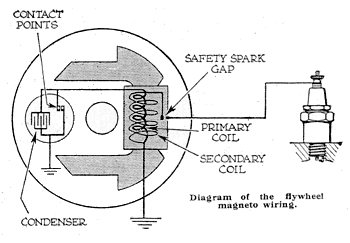 |
The whole arrangement was extremely reliable. Apart from
the spark plug, the only item that needed occasional attention was the
contact points in the contact breaker.
The points needed to be kept
clean and the gap correctly set. Failure to maintain a sufficient gap
led to overheating and considerable difficulty in starting. |
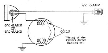
| The wiring diagram of the simple lighting set which did
not include a battery. It produced an A.C. voltage to light the head
lamp and tail lamp.
Due to the special winding of the coils, a rapid
rise of voltage was obtained. This was almost constant over 25m.p.h. |
 |
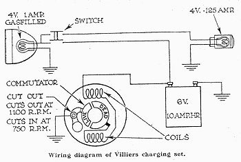 |
The charging set rectified the A.C. voltage induced in
the lighting coils by a commutator, which was carried on the flywheel.
A
centrifugal cut-out was mounted on the flywheel to prevent the battery
discharging through the lighting coils, when the flywheel was
stationary. A Nife accumulator was used which needed to be topped up
with distilled water instead of acid. |
| Care was required when doing this, as the liquid
electrolyte contained caustic potash which would attack the hands or
clothes. |
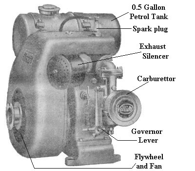
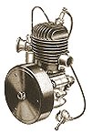
The Villiers Mk.10 stationary engine. |
The Mk. 10 Villiers stationary engine was a typical
Villiers product. It was simple, neat and compact, with few moving
parts. Because of this simplicity, Villiers engines were reliable and
easy to maintain. The engine included the Villiers flywheel magneto,
with the engine cooling fan mounted on the outside of the flywheel.
Most
of the parts were made in-house and additional parts were available for
petrol-paraffin running. |
| The engine had a 50mm bore and a 50mm stroke. The total
swept volume was 98c.c. and the engine could deliver 1h.p. at
2,000r.p.m., and 1.3h.p. at 3,000r.p.m. It was air-cooled and used an
oil-wetted type of air filter.
The capacity of the fuel tank was 0.5
gallons and the lubricating oil sump held one pint. It was fitted with a
Lodge spark plug and Villiers carburettor. |
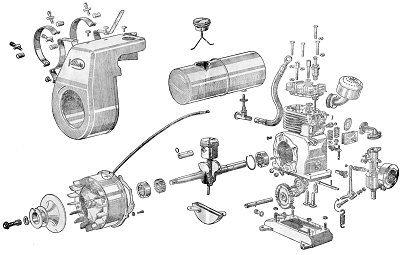
A drawing showing the parts that make up the
Mk.10. |

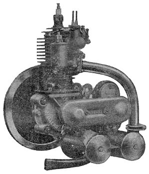
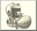
The Villiers Mark 3 engine. |
The Villiers Mark 3 engine was introduced in 1920 and
was one of the last engines made by the company before the introduction
of the flywheel magneto. It used the conventional type of chain-driven
magneto with horse-shoe magnets and a conventional flywheel.
The engine
was designed to allow easy access to the various parts for servicing.
The carburettor was attached almost at the top of the cylinder wall to
allow access to the jet. The spark plug was moved to the top of the
cylinder, to isolate it from the top cooling flange and it kept
remarkably cool.
The inlet gas was led through an induction passage,
cast into the cylinder assembly. This arrangement avoided condensation
and gave greater efficiency because the gas was warmed on its way to the
crank case. Like many Villiers engines, it included double silencers and
was very quiet in operation. |
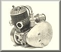
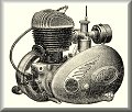
Another view of
the Mark 3. |
 |
 |
|
 |
|
 |
| Return
to Other Products |
|
Return
to the beginning |
|
Proceed
to Villiers adverts |
|