|
This is a sequel to the other article about the factory, and was written about
two years later. It also appeared in 'The Automobile Engineer'.
The Works of the Sunbeam Motor Car Company
Limited
Recent Developments in the Practice of a Well-Known Firm.
A brief description of the
Sunbeam Works at Wolverhampton was given in the
issue of The Automobile Engineer for January, 1924.
Since that date important extensions have been made
to the factory, and in certain directions the
production methods have been improved. Modern plant
has also been installed for gear grinding, as well
as for the finishing operations on pistons, gudgeon
pins, and other parts which call for a high degree
of accuracy.
Originally the company
manufactured several models, but they have now
decided to concentrate on the 14hp. and 20hp. and 3
litre cars. The output of these three types is
approximately fifty per week. In addition, a limited
number of the new 30hp. model are being built. This
car was shown for the first time at the recent Motor
Show at Olympia. It is a particularly fine model,
built on the same general lines as the smaller cars,
except that it has an eight-cylinder engine.
The most important additions to
the works consist of a new machine shop and a
water-raising plant, by means of which an adequate
supply of water for all purposes in the factory may
be obtained if necessary. Few automobile firms
experience any difficulty in this direction, but the
scheme adopted by the Sunbeam Company is of interest as an example of
enterprise in overcoming unusual obstacles. |
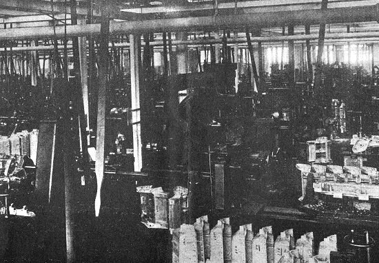
Fig. 1. A view of the new machine
shop.
|
Owing to the high ground on
which the works is situated, and the uncertainty of
the water supply in the neighbourhood, an expert was
consulted as to the advisability of sinking an
artesian well. As the result of this it was decided
to undertake boring operations on the company's
premises, and after reaching a depth of 301ft. an
adequate supply of water was tapped.
The bore hole
passes through strata consisting of conglomerate,
hard red marl, soft red marl, sandy marl, and
sandstone. The lower 200ft. is lined with a steel
casing tube 10in. in diameter, whilst a 12in.
diameter tube is used for the upper portion. In the
portion of the bore which passes through sandstone,
perforated casing tubes are used to allow a free
flow of water. Plain tubes are inserted through the
strata of sandy and soft marl to prevent any
movement which might take place with the soft earth
falling into the bottom of the bore.
The pumping plant consists of a
Broom & Wade air compressor driven by a 30hp.
electric motor in conjunction with two Rees Roturbo
rotary pumps, each direct coupled to a 10hp. motor.
The two rotary pumps have a combined capacity of
24,000 gallons per hour. In addition, a single motor
and pump is installed as a stand-by.
A storage tank is situated in
the pump room at the head of the bore hole, from
which the water is raised by an air and water main
extending to a depth of 170ft. from the surface. The
air pipe is l½in. diameter, whilst the water main is
4½in. diameter, and these are connected together by
a specially designed foot piece, so that the water
is raised by air pressure. From the storage tank the
water is raised to a reinforced concrete storage
tower by the rotary pumps, which deliver through
2,450ft. of 6in. main. The base of the storage tower
is 30ft. above ground level, and it has a capacity
of 30,000 gallons.
To supply the works, the
delivery main from the pump room to the storage
tower is tapped at various points and
connected to the existing pipe line. The
yield from the bore hole varies as the head of water
on the air pipe, being 12,250 gallons per hour with
water at ground level, whilst after twenty four hours'
continuous running the yield was 10,000 gallons per
hour, the water level then being 67ft.
from the surface. A float switch fitted between the
motor starter and the storage tank provides
automatic control of the pump, so that its delivery
shall synchronise with the yield from the bore hole.
It will be apparent that the
installation is quite an elaborate one, and has been carried through with every care
and thoroughness. |
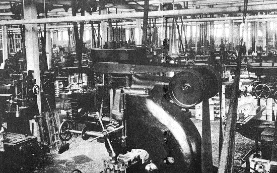
Fig. 2. Another section of the new
machine shop.
|
The new machine shop is a
lofty, well lighted building with a floor area of
48,024 sq. ft. Two views of the shop taken in
opposite directions from a point near the centre are
shown in figs. 1 and 2, though it is difficult to
obtain a photograph showing the full extent of the
shop, owing to the disposition of the machines and
the intervening belts and girders. Incidentally, it
may be remarked as somewhat surprising that more of
the machine tools have not been equipped with
individual motor drives.
An interesting point in the
layout of the shop is the provision of two side
galleries, each of which has an area of 3,312 sq.
ft. These accommodate the lighter units of the
plant, such as small automatics, capstans, brass
finishing lathes, etc. Thus pistons and other
comparatively small parts can conveniently be
produced in the same shop as the larger components. It
may be mentioned that pistons are at present
finished on the outside diameter by grinding,
machines having been installed in one of the
galleries for this purpose. The limit worked to is
exceptionally fine.
On the floor of the new shop,
the heavier plant is laid out as far as possible
according to the sequence of operations. Cylinders,
crank cases, gear boxes, rear axle cases, and
crankshafts are dealt with in this department. A
small section is also devoted to gear grinding. Many
of the machining operations on the larger components
were described in the previous article dealing with
the Sunbeam Works, so that further reference to them
is unnecessary except in cases where the methods
have been revised.
|
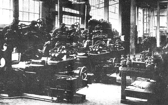
Fig. 3. A battery of Maag gear
grinders.
|
The gear grinding plant is a
comparatively recent introduction, and consists of
three Maag machines arranged as shown in fig. 3.
Apart from the relative merits of these machines as
compared with the Lees-Bradner and other gear
grinders which are being installed by auto mobile
manufacturers, mention may be made of one or two
interesting points in connection with the Maag
machine.
Amongst other things, the use
of small abrasive wheels facilitates the grinding of
cluster gears and such work as that shown on the
table in front of the machines. It is also possible
to employ two wheels for grinding both sides of the
teeth simultaneously, the faces of the wheels being
inclined at an angle equal to the pressure angle of
the gear to be ground. The two faces thus correspond
to the sides of a rack tooth.
Saucer-shaped wheels are
employed, the comparatively heavy wear on the small
wheel face being taken up automatically by an
ingenious electrical device. This consists
essentially of a diamond contact which is advanced
to meet the wheel face at short intervals. As soon
as appreciable wear has taken place, the diamond, in
making contact with the wheel, overshoots a
predetermined point, and in so doing it closes an
electrical circuit, which operates a sensitive
compensating device. This imparts a slight axial
movement to the wheel spindle, which continues until
the wheel face is brought back to its original
position, when the feeding motion is automatically
disengaged. In practice, of course, the movement is
made in very small steps, so that the product is
uniform within the fine limits which are permissible
on this class of work.
|
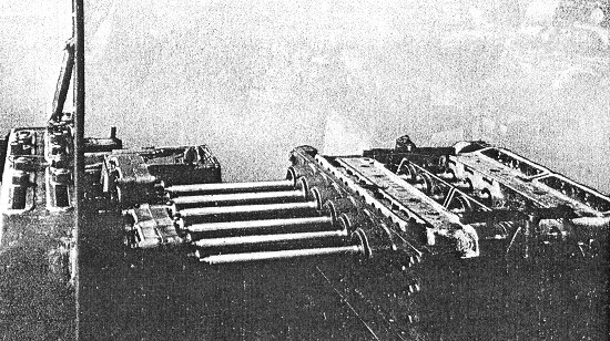
Fig. 4. Boring 20hp. cylinder
blocks.
|
The equipment for handling the
larger components in this shop has in many cases
been designed for dealing with two or more
components at one setting. This applies to the
majority of the milling operations on the cylinder
blocks and cylinder heads, as well as to the
operation of machining the cylinder bores.
The
machine employed for this operation is illustrated
in fig. 4, the component being the cylinder block
for the 20hp. engine. It may be seen that a fixture
of unusually large size is mounted on the work
table, so that it accommodates two six-cylinder
blocks simultaneously. The machine is one supplied
by G. A. Alexander & Co., Ltd., Birmingham, although
it differs somewhat from their usual range of
cylinder boring machines, having been specially
designed for the work in question.
Attention may be directed to
the massive construction of the fixture, which is
made with a central wall so that the boring bars can
be piloted in the centre as well as at both ends.
Two separate cutters on each bar are employed for
boring both cylinder blocks simultaneously, and the
same machine is used for roughing and finishing
cuts, the bores being finally finished by grinding
on Heald machines.
Another interesting operation
on the cylinder blocks is the milling of the
inspection cover facings. Actually this operation is
carried out prior to boring the cylinders and after
the bottom faces have been milled, Owing to the fact
that the inspection cover faces are inclined to the
vertical, two conical milling cutters, mounted side
by side, are employed for milling the
facings on two cylinder blocks simultaneously.
|
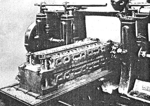
Fig. 5. A multiple fixture for
milling cylinders.
|
Another component on which some
interesting operations are carried out is the
water-cooled cylinder head. This is an intricate
casting, calling for much more careful treatment
than the usual type of detachable head. After heat
treating, the top and bottom faces are finished,
this operation being now performed by surface
grinding in place of the former method of milling
the faces. The bolt holes and valve guide holes are
then drilled at two separate settings on a
multiple-spindle machine, after which the holes are
drilled and tapped on a radial for taking the unions
by means of which the casting is coupled up for the
water test.
A further drilling, facing, and tapping
operation is also carried out on the sparking plug
holes prior to milling the inlet and exhaust faces.
The last-named operation is carried out on a Hendey
duplex milling machine in the manner shown in fig.
5. This affords an excellent example of the type of
multiple fixture employed by the Sunbeam Co. for
handling large components.
The fixture takes the
form of a substantial box casting open at the sides
so that four castings can be milled simultaneously
by means of inserted tooth cutters, which are
sufficiently large to machine the two sets of
facings with one traverse of the work table.
Following this operation, the inlet, exhaust, and
rocker stud holes, as well as the drain hole, are
drilled on an Archdale machine, and the casting is
next transferred to a vertical miller for machining
the combustion chambers. Boring the valve pockets on
a radial then completes the component apart from
testing. |
|
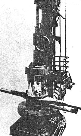
Fig. 6. A typical
multi-spindle drill head. |
Extensive use is made in this
department of multiple-spindle drill heads fitted to
single-spindle machines. One of these is illustrated
in fig. 6, which shows the equipment for drilling
the bolt holes in rear axle casings.
The component
is a steel pressing, which is first of all machined
on the ends, after which it is mounted in a large
face plate fixture for facing and boring the central
portion to take the differential housing.
It should
be noted that, in the operation of turning the
centre, multiple tools are employed, so that both
sides of the casing can be machined at one setting,
thus avoiding the necessity for reversing the work
in the fixture.
The head employed for the
drilling operation is of light construction with
ball bearing spindles, the driving gears being
enclosed in a simple sheet metal casing.
|
|
On this particular component
drilling is carried out from both sides, the two jig plates being clamped in
position by a central bolt and nut, whilst feet are
provided for the fixture to raise it
clear of the work table. The same head is also
employed for drilling the rear axle cover and the
housing which is bolted to the rear axle casing, the
fixture employed in this case being a plate which is
supported on pillars so that the component may be
clamped upwards against the underside of the jig
plate. |
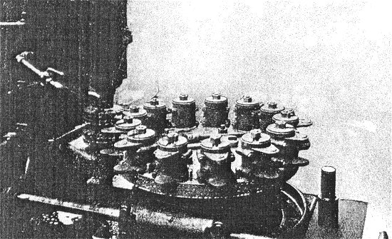
Fig. 7. Milling spring brackets.
|
Another type of tool equipment
which is employed extensively in the Sunbeam works
is the rotary continuous milling fixture. Two
examples of typical operations are shown in figs. 7
and 8, these being representative of a large number
of similar operations on such components as
brackets, forks, small casings and covers, stub
axles, etc. The method is employed to a much greater
extent than in the majority of automobile factories
despite the fact that the number required of any one
component is relatively small. The moderate outputs
are dealt with by making the fixtures comparatively
simple and arranging them so that they can be
quickly changed on the machine tables.
The component shown in fig. 7
is the rear spring bracket and cap, and it will be
observed that a gang of cutters is employed for
finishing both the inside and outside faces of the
two lugs simultaneously. Previous operations consist
of milling the faces of the two halves, milling the
bosses for the bolt holes, and bedding and bolting
up the cap ready for boring. The milling operation
is, however, carried out before finishing the bore.
The components are located in the fixture shown by
spigots, which are a loose fit, whilst the studs
projecting from the base of the fixture prevent the
parts from rotating about the spigots under the
action of the cutters. A substantial bracket bolted
to the column of the machine supports the lower end
of the cutter arbor, thus effectively preventing any
possibility of springing.
|
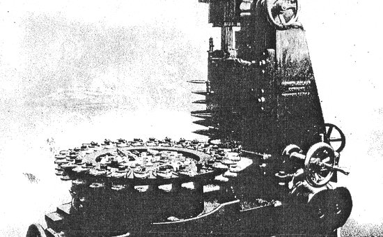
Fig. 8. A typical rotary milling
machine.
| In the case of the component
illustrated in fig. 8, which is the cover for the
brake cam, the fixture is made to accommodate
fifty-two pieces by arranging for the components to
be clamped simultaneously to the upper and lower
side of a projecting flange. A gang of four cutters
is used, as in the previous example, together with a
support to ensure rigidity of the arbor. The
machines employed for this class of work include
chiefly Barber-Colman, Herbert No. 6, and Becker
vertical millers. With regard to the erection of the
Sunbeam chassis, no attempt has been made to carry
out the work on an assembly track. Such methods are,
of course, of doubtful value, unless an output
running into hundreds per week can be obtained. In
addition, the firm hold the opinion that the
practice is not applicable to the production of a
high-grade car. Instead, the wheels, complete with
tyres, are bolted in position at an early stage, so
that the chassis may easily be moved along the shop
as it nears completion.
Runways extending throughout
the assembly shop also facilitate the handling of
heavy units. These runways may be seen in fig. 9,
which illustrates one section of the erecting shop.
Separate tests are carried out on the engine, gear
box, and rear axle prior to assembly, whilst the
completed chassis is submitted to a severe road test
before commencing coach building or body fitting. |
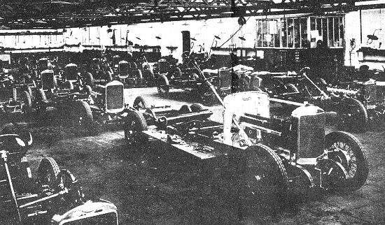
Fig. 9. A portion of the erecting
shop.
|
In conclusion, it may be
mentioned that the social side of the organisation
has received its share of attention in the
improvements which have been made, a well-ordered
institute and sports ground having been provided for
the convenience of the Sunbeam employees.
|
 |
Return to
the
previous page |
|