Ploughing Machines 2
|
John Smith was very much in favour of a
balanced boiler, which was pivoted around a central point and could be
tipped forwards or backwards via a worm gear and a handle on the back of
the boiler, near the regulator. The boiler was balanced on two trunnion
blocks, which were mounted on the frame. The idea was that when the
vehicle travelled up or down hill, the boiler could be adjusted so that
water always covered the firebox crown plate. A spirit level was
supplied for the purpose. It is not known if a Smith engine ever
suffered from an overheated crown plate, but many complications were
introduced into the design because of this. John Smith took out a patent
for two designs of balanced boiler and his rear axle clips, on August
7th,
1858. The patent number was 1799 and was titled “Agricultural steam
engines and locomotive steam engine to be used on common roads”.
In July 1859 John Smith
exhibited some of his products at the Royal Agricultural Society
of England’s Show at Warwick. He displayed a 12 hp. traction
engine which was fitted with his patent boiler and reversing
straps and was priced at £420.
|
|
The location of the Village Foundry. |
He also exhibited a 12 hp. horse-steered steam
plough, which came complete with a windlass and was priced at
£780. A third exhibit was a windlass that was built at Coven to
Fowler’s design. Sales were good and it was decided that a
larger works was required. In 1860 the Village Foundry was built
on the corner of Brewood Road and Lawn Lane. The Smith family
already had a cottage in Lawn Lane next to the Wesleyan
Methodist Chapel. The new works occupied the land in-between the
cottage and Brewood Road. The main building, known as the
machine shop had 5 bays, at least two of which were fitted with
large heavy sliding doors. Above the machine shop in the loft
was the pattern shop, which was also used as a village Sunday
school. Next to the machine shop was the foundry and the
blacksmith’s shop. There was also a separate boiler shop near to
the chapel. |
|
In July 1860 John Smith displayed a
10 hp. steam ploughing engine at
the Royal Agricultural Society of England’s Show at Canterbury. It was
fitted with a winding drum underneath the boiler, which was driven off
the crankshaft by a short vertical shaft and bevel gear. The machine
achieved 7 m.p.h. fully laden and 20 m.p.h. when empty. It was priced at
£720.
Repairs to other makes of traction
engine were also carried out at the Village Foundry. On 13th
October, 1860 John Smith left the works to deliver a customer’s machine
that had been in for repair. On the journey the boiler exploded and blew
him through a hedge. He was scalded on his legs, but could so easily
have been killed.
|
| In 1861 John Smith went into partnership with John
Birch Higgs, a local man from Brewood. Higgs eventually became
Smith’s brother-in- law. In the same year they took out two
joint-patents for improvements in threshing machines (patent
numbers 757 and 3188). One of their machines utilising these
improvements was exhibited at the Royal Agricultural Society of
England’s 1861 Show at Leeds. They also displayed a 10 hp. two
cylinder traction engine with a balanced boiler and iron wheels,
price £395. |
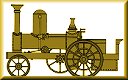
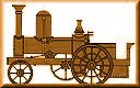
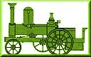
A Smith traction engine with a balanced
boiler. |
| Smith and Higgs also exhibited the following year
at the Royal Agricultural Society of England’s Show at
Battersea. They displayed a 7 hp., single cylinder traction
engine with an overtype engine and a large steam dome. Large
steam domes became a standard feature of the company’s products.
The 6 ft diameter driving wheels were belt driven and two speeds
were available. The engine had a 4 ft diameter flywheel which ran
at 150 rpm. when driving a belt. |
|
Steam Locomotion on
Common Roads. The Engineer, 4th September, 1896.
It is interesting to note that one
of the first traction engines ever made was of the
locomotive pattern. The two cylinders were placed
beneath the smokebox, the engine working below the
boiler barrel. The engine was made by Messrs.
Ransomes and May, now Messrs. Ransomes, Sims, and
Jefferies, Ipswich, and exhibited at the Norwich
Show in 1849.
Nine years later Mr. John
Smith, junior, of Coven, near Wolverhampton,
patented the road locomotive that has been several
times referred to by The Engineer. This engine
certainly deserves a full description. The patent is
dated 1858, No. 1790. Fig. 3 shows a side elevation,
Fig. 4 gives an end view of the engine, while Fig. 5
illustrates the trunnion on which the boiler rested.
An old engraving I have before me has the following
description:
The engraving represents Smith
and Higg's patent locomotive steam engine, to travel
on the ordinary roads without horses. It has been
practically tested for three years, and is fully
appreciated by those who have been saved much horse
labour. It consists of an 8-horse power locomotive
steam engine, fitted with patent adjusting boiler,
so constructed as to keep the water always on a
level when going on hilly roads, thereby preventing
priming or burning the firebox or tubes. It is also
fitted with frictional straps for actuating one or
both of the hind road wheels.
It will be seen from Fig. 3
that two deep side plates of wrought iron run the
whole length of the engine and tender. The two
cylinders, 6½in . diameter and 10in. stroke, are
bolted between these plates beneath the smokebox.
The crank shaft is placed as near to the saddle
plate of the boiler as possible, so as to obtain
long connecting rods; the bearings for the crank
shaft are let into the side plates. On one end of
the crank shaft a small chain pinion is keyed, which
drives a largo chain wheel keyed to the axle; the
ratio of the chain driving gear is 9 to 1.
The axle is fixed beneath the
fire hole door, and is mounted on a pair of good
springs carried by the side plates. Strong wood
wheels are shown; the drivers are 6ft. diameter,
having twelve spokes, connected together in the
centre of their length by a wrought iron ring. The
leading wheels and under carriage are made of wood.
Here are the three commendable features which
produce a silent running engine, wood wheels, chain
driving gear, and a good arrangement of springs. I
have been particularly pleased with the silent
manner in which some of the old wood wheel, chain
driven and light self moving engines have passed
over ordinary roads at moderate speeds. Unless you
happened to see the engine you would not know that a
road locomotive was passing your dwelling. If a
modern road locomotive engine traverses the same
road, at the same speed, the noise and vibration, it
must be admitted are anything but pleasant, and to
many persons are a real source of irritation. I
trust, however, that the coming road engines will be
no more a nuisance than were the old types referred
to.
Mr. Smith introduced the
frictional straps, by means of which the axle would
drive one or both of the main wheels; these straps
were very extensively used on ploughing engines
until quite recently. From Figs 3 and 4 it will be
seen that the boiler is pivoted on a casting carried
by the side plates. The boiler could be maintained
in a horizontal position by means of a screw and
hand wheel, while the engine was traversing hilly
roads. It was found however, that this arrangement
was not needed in practice. A large dome is adopted,
from the top of which the steam is conducted to the
trunnion, and from thence to the cylinder. The
trunnion on the opposite side served as the
feed-water supply pipe. Fig. 5 illustrates this
detail. The admission of the steam is controlled by
a gland cock. A flywheel is keyed to the overhanging
end of the crank shaft; the engine is fitted with
link motion reversing gear and a set of governors.
 |
The steersman is provided with a seat in
close proximity to the chimney and the hot
smokebox, but judging by the expression on
the face of the individual who occupies this
responsible seat, no discomfiture is
realised.
The weight of the engine and boiler are
exceedingly well distributed fore and aft. A
door is provided for ready access to a roomy
footplate; beneath this footplate is the
feed water tank. The boiler is of the raised
firebox locomotive type, and the working
pressure is 100 lb. per square inch.
It is stated that a counter shaft was
added to one of the engines made by Mr.
Smith, with spur gearing between the crank
shaft and the intermediate shaft.
This engine is reported to have travelled
six miles at the rate of eight miles an
hour, and was eventually sent into the
neighbourhood of Bristol. |
| The Engineer said: "This was one of the
best traction engines we have ever seen."
And again: "It became one of the most
satisfactory traction engines we ever saw."
It is also written: "Such an engine was
built by the late Mr. Smith, and was
perfectly successful." Considering the date
when this engine was built, it is a most
creditable piece of designing, and perfectly
fulfilled some of the vital requirements of
road locomotive engines. |
 |
|
|
|
The Royal Agricultural Society’s Show in Battersea
Park. The Engineer, 27th June, 1862.
Among the other self-propelling
engines is one, the Bee, by Mr. Smith, of Coven,
combining some good points. In several respects it
is an incomplete copy of Mr. Aveling's engine. The
weight is kept well upon the driving wheel, and the
cylinder is placed on the top of the boiler towards
the smoke box, just at the back, however, of a large
steam dome. The cylinder is 8½in. in diameter, and
10in. stroke, the whole weight of the engine, empty,
being about 6 tons. The steering gear is in front,
and occupies but little room. The driving wheels are
6ft. in diameter, and only 8in. wide. A friction
strap is placed on the back of each, and through
this strap all the power is applied. The gearing is
for slow and quick speeds, the geared wheels being
too light for much service. The driving axle is
4½in. in diameter. This engine is employed to drive
a thrashing machine, and in this are two fans
drawing hot air, through a series of large and
readily connected pipes, from the firebox of the
engine, the object being to dry the grain in the
process of thrashing. There are but two belts on the
whole machine. Some practical farmers prefer this
arrangement to Bruckshaw and Underhill's fan blast,
now extensively adopted by implement makers. |
|
|
An article from The
Engineer, 10th October, 1862.
This invention, by John Smith,
senior, of Coven, near Wolverhampton, has for its
object improvements in drying wheat and other grain.
Figs. 1 and 2 represent an arrangement for carrying
out the invention; Fig. l shows a portion of a
thrashing machine, in which the grain is drawn up by
the exhaustive action of a fan; and Fig. 2 is a
vertical section of the fan. a is the fan; b is the
tube through which the heated air enters the box c,
into which the grain is admitted by the spout d for
the purpose of being elevated to other parts or the
thrashing machine.
The corn is delivered from the
spout d into the hopper e, and surrounds the lower
edge of the suction tube f, which is fixed so as to
leave half an inch space for the full inlet of the
grain into the suction tube. The hot air rushes from
the box c into the tube f along with the corn, and
both are drawn into the fan at the centre, as shown
in Fig. 2, and are thence delivered to other parts
of the threshing machine by the spout g, Fig. 1.
It may be sometimes found
convenient (when a portable steam engine is used for
thrashing) to connect the tube b with the smokebox
of the engine, in order to obtain a supply of heated
air, but the heated air may be otherwise obtained, a
separate fire being used to heat it. There is a
slide by which cold air can be admitted to the hot
air pipe, so that the heat of the current of air to
which the grain is exposed may be regulated as may
appear necessary. |
|
|
An article from The
Engineer, 26th December, 1862.
This invention, by John Smith,
of Coven, near Wolverhampton, has for its object
improvements in thrashing machines. In a former
provisional specification filed by him, and dated
the 28th of February last, he described an invention
consisting (in part) in artificially heating the
current of air which is employed for raising the
grain from the lower part of the thrashing machine
to the upper.
He has since discovered that a
current of artificially heated air may also be
usefully applied in a threshing machine in the
following manner. The current of artificially heated
air may be employed in winnowing the grain as it
passes over the riddles and falls from riddle to
riddle; or, where the grain is raised by a
mechanical elevator, in place of by a current of
air, the artificially heated air may be made to pass
along the elevator trunk. Or a current of
artificially heated air may be made to pass through
the barley hummeller, which is a horizontal or
inclined passage through which the grain passes, and
where it is kept in constant motion by revolving
instruments, which by the friction they produce
brighten the grain and in the case of barley knock
off the spike.
Or the grain may be made to
descend a passage or spout traversed by a current of
artificially heated air, which may then, if desired,
be used to separate the light from the heavier
grains, as is in some cases practised, or the
passage or spout may be placed horizontally, and the
grain may be carried along it by a screw or other
similar instrument, or the current of air may be
sufficiently strong to carry the grain with it. In
all cases, however, in which a current of
artificially heated air is used in conjunction with
thrashing machines, it has been found most
advantageous to obtain the artificially heated air
required by causing a fan to draw its supply of air
from the smoke box or flue of the engine employed to
drive the thrashing machine. In some cases the grain
as it passes from one part of a thrashing machine to
another is caused to pass through a passage
surrounded by a steam jacket, or heated by steam
pipes or cases, and the steam jackets, pipes, or
cases are connected by suitable pipes with the
boiler of the engine. |
|
|
|
|
|
|
Return to the
Previous page |
|
Return to
the contents |
|
Proceed to
the next page |
|