|
The Mechanical Filtration and Softening of
Water
|
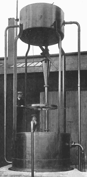
The mechanical filter. |
|
The most
frequently adopted method of
filtering water is that of slow sand
filtration, which requires a large
area of land and a small filtering
bed, the rate of filtration varying
between one and four million gallons
per acre per day.
In places where
the price of land renders this
system impracticable, and where the
cost of the filters is a matter of
consideration, mechanical filters
can be substituted, as they not only
take up very considerably less
space, but also compare very
favourably with the slow sand
filters as regards working costs. It
should be pointed out that the term
"mechanical" here applies to the
means adopted for cleansing the
filtering material.
There are two
principal methods of cleansing in
use. In one, the water is caused to
flow through the filter bed in the
opposite direction to that in which
filtration usually occurs, air being
also injected underneath the bed. In
the other the reverse flush of water
is used simultaneously with a
mechanical agitator.
Some makers
introduce the necessary air by means
of a steam injector. In the
apparatus we are about to describe,
which is made by Rubery, Owen and
Co., Darlaston, the steam jet is
done away with and the reverse flush
itself is utilised to inject the
air. In addition, a hand-operated
agitator is provided, so that the
filtering material is thoroughly
broken up and a uniform contact with
the air results. |
|
The header tank
A contains a supply of clean
water which flows through pipe B
into the cone D from where
the water carries a current of air
from openings T1
and T2 into space
F, beneath the filters H.
The filters
have been specially designed for the
bacterial purification of water for
town supplies, and are employed in
conjunction with coagulants, by
means of which a film is formed on
the bed artificially. The coagulant
is introduced into the pipe which
supplies the filter with water.
The makers
claim that, owing to the filter
being covered, the growth of algae
is prevented, and the formation of
the desired film is under control,
the time required for the growing
process being only a few minutes.
The water and
air pass upwards through the
filtering material, and the air
finally escapes by way of an air
pipe not shown. |
|
A sectional elevation of the
mechanical filter. |
|
The unfiltered
water enters at P, and the
filtered water passes through the
filtering medium H and
perforated filtering plate G,
fitted with specially constructed
screening chambers and gauze
screens. The filtered water flows
into the header tank via pipe U
and flows out of the header tank
through pipe L. Wheel S
allows the filter to be agitated. |
| |
|
|
|
 |
|
 |
|
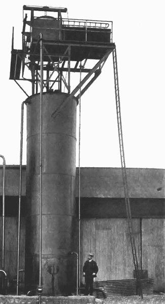
The Andrews
Water Softener. |
Andrew's patented
water-softening plant is another device made
by the same firm. The plant illustrated in
the photograph has been erected at Messrs.
Rubery and Owen 's works at Darlaston where
it is effectually reducing hard water of
from 54 deg. to 6 deg. of hardness. It can
soften 5,000 gallons of water per hour.
The hard water enters
header tank A and flows out through
valve B into cone J where it
is mixed with milk of lime from the chemical
tank H via pipe R, and air.
The passage of the water and chemicals
together down pipe S and cylinder
L, together with the impact against the
baffle-plate K and the addition of
air ensures an intimate mixing of the whole.
The treated water next passes through the
openings in the bottom of the cylinder L
and the stand pipe T to the sand
filter U where it is deprived of its
precipitate, consisting of a powder which
would otherwise find its way into the
boiler. When header tank A has
emptied, the fall of the float C
brings the tripping gear into action and the
positions of the passages in the two-way
valve B are reversed. The header tank
again fills, and when full, valve B
operates and the whole process starts again.
The tripping gear. |
