|
Some New Features
in Moto-Vehicle Design by Thomas Hugh Parker
From the March 1899 edition
of The Automotor and Horseless Vehicle Journal
An Excerpt from a
paper read before the Liverpool Self-Propelled Traffic
Association
by Mr. Thomas Hugh Parker, on 28th February 1899
Some two and a half years ago, I was spending my time
supervising the erection of electrical and general plant in the
Transvaal goldfields. and the necessity for an efficient motor
controller often presented itself to me. After giving some
considerable time and thought to the problem, I obtained a
satisfactory result, and communicated the idea, by means of
drawings, to my father, Mr. Thomas Parker, at Wolverhampton, for use
in the factory. Soon after this, I heard the pleasing news that a
Bill was to be presented to Parliament to allow of mechanical road
locomotion in England, and was not long in grasping the fact that
the controller would also adapt itself to controlling electrical
road vehicles. Fired with this idea, and wishing to be in the first
swim of a new industry, I started for England, and immediately after
my arrival in Wolverhampton set to work designing an electric car.
I selected a section of road over which it was obvious the car
would have to run, viz., between my father's house at Tettenhall
and the town of Wolverhampton, a distance of 2.5 miles without a
single yard of level ground in its length, the gradients varying
from 1 in 120 to 1 in 15. The first difficulty that presented
itself was to obtain data to work upon. My idea was that 12 cwt.
would be more than a reasonable. weight to allow for an unloaded
electric car for six passengers, and the nearest article I could
find of this weight was my father's brougham. I procured a large
spring balance, and set out at daybreak to map out a curve of
the force required to draw the brougham over the track. We took
the shafts off and attached the horse with the spring balance
inserted between the animal and the vehicle, and not until that
December morning had I fully realised the power of a horse,
although I have had to deal with them nearly all my life. My
dream of 12 cwt. was at an end, for, after carefully working out
all points, the weight totaled up to a minimum of 25 cwt. for a
three hours' run at eight miles per hour.
Having determined the approximate power required, the next most
important problem was the design of the motor and gearing.
|
|
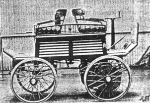
Figure 1. A small electric dog-cart with
double bogie steering. Courtesy of the late Jim Boulton. |
After a great deal of discussion amongst the members
of the family, it was decided that it would be preferable to use two
motors coupled by means of single or double reduction gear, running
in oil, ever required, to the hind wheels, in preference to using a
single motor and differential gear. Double spur gearing did not work
in well with the design, the result of which decision was that
chains had to be used on the second reduction, necessitating the use
of eccentrics for taking up the slack or stretch of the chains, and
two frames to support the motors separately. |
| These first motors were series wound, and designed
to run at 950 revs. per minute, and give a torque effort of 30 lbs.
on the periphery of each armature with a current of 25 amperes.
Forty was chosen as the number of cells, to permit of their being
charged in series on the usual 110 volt circuit. The controlling of
the car came next. To do this without the use of resistance coils
was a difficult matter at first, but eventually turned out to
be one of the simplest. Three speeds forward and one backward were
found to meet all requirements, and these variations were obtained
by dividing the cells into two groups of 20 each. The three forward
movements were obtained as follows: First, by putting batteries in
parallel, motors in series, giving two miles per hour;
second, batteries series, motors
series, four miles per hour; and third, batteries series,
motors parallel, eight miles per hour. The one backward movement,
batteries parallel, motors series, with current in the armatures
reversed, two miles per hour. The whole of the operations were
carried out, by means of the controller mentioned at the beginning
of this paper with less than one single turn of the handle.
The steering gear presented itself next. I had heard a great
deal of what had been done, and had seen a car with Ackermann
gear, but was dissatisfied with it, and also the double cycle
head arrangement. I wanted a steering gear that would admit of a
car running round a small circle with as little resistance as
going straight ahead, and, after a great deal of scheming
devised the idea of moving both front and hind wheels in
opposite directions at the same time and through the same angle,
which, both in model and practical form, worked splendidly. It
enabled the car to be turned in its own length without turning
the wheels under the body, and is naturally doubly as sensitive
as a single bogie or broken axle gear. Another great advantage
is that it admits of all four wheels being driven, and the load
being equally divided on all four wheels. It gives a good
support to the bottom of the vehicle, which in most cases is
made quite flat. Each wheel can be provided with a brake.
A careful examination was made of the various types of
batteries, and it was decided to give the Blot Company the order
for the first set. Having overcome the various points of
difficulty on paper, some premises were rented in which it was
just possible to build and put the car together, and as the
weight of the car grew we had to shore the floor up from
beneath. Six weeks from the day we commenced, the car was ready
to be launched. I say launched, because it had to be lowered 18
inches into the square, down some planks. |
| Somehow the news leaked out that a trial was to take
place, and we found a large crowd of people waiting outside when the
doors were taken down, as there was not sufficient room to open them
when the car was inside. You may judge from this how much chance we
had to make a private trial. However, she was launched and ran a 10
mile trip, with nine people aboard, without a hitch. During the
journey we had occasion to descend some very stiff gradients, and I
found, although I bad some powerful brakes upon the car, it was with
great difficulty I could restrain it from getting the better of me. |
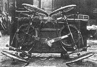
Figure 2. A view of the bottom of the small
double bogie car with axles turned to their extreme angle. Courtesy
of the late Jim Boulton. |
| Although I did not say anything to the passengers,
I decided before the journey was finished not to attempt another
trip with series motors. I had the motors dismounted and had them
shunt wound, and, needless to say, had to stand a good deal of chaff
for such a thing, as running shunt motors in conjunction with
storage batteries on tramways had years ago been given up as
impracticable. The motors were hung on the third day, the
connections were made, and the car ran down into the street, the
result being beyond expectation. Instead of the sudden rush of
current as at starting with the series motors, viz., 50 amperes, the
car moved steadily away with less than 10 amperes, although the
current was about the same when the rate of travelling accelerated.
We then proceeded to take some tests on an incline. To do this we
ran the double journey to Tettenhall and back. The work of
manipulating the car was very much reduced, it only being necessary
to set it to the required speed and look out for obstacles. On
descending the stiffest hill the speed did not increase 5 per cent.,
and it was very gratifying to see the ampere meter reading 20
amperes to the good, charging the batteries instead of wearing the
brake blocks away. In case of need it was found possible to bring
the car to a stand from full speed ahead in 3 feet on a 10 per cent.
gradient, without the use of the brake or reversing the motors. This
original car has been running almost daily for the past 18 months
exactly as it was made, without a single breakdown, and has carried
some of the most eminent men of the century upon it.
I will now proceed to describe a few lantern slides I have had
prepared under difficulties for you, showing the various stages
of progress. |
| The original controller is adapted for use with
shunt motors working on ordinary high tension circuits, to enable
three movements to be made consecutively with one handle, locking
and interlocking each movement. There are two rollers or discs fixed
to the centre spindle, actuating two levers connected to the two
switches, top and bottom. In starting from zero, the one disc, which
is slightly in advance of the other, first puts on the shunt switch
and locks it on, leaving the handle free to turn a full revolution
in the same direction. |
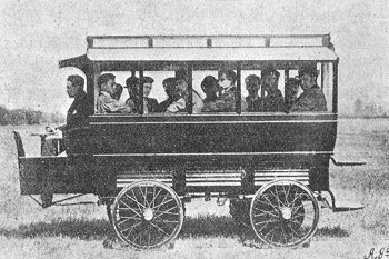
Figure 3. A 14-seater omnibus. Courtesy of
the late Jim Boulton. |
| The next portion of the revolution puts on the main
switch and locks it on, allowing the main current to flow through
the armature with resistance in the circuit. This resistance is
determined by the switch arm carried on the centre spindle below the
discs working on an ordinary divided resistance ring, and, in this
case, admits 24 points of regulation in a single turn of the handle.
When stopping the motor, it follows that the maximum resistance must
be put into the circuit ready for starting. Again, the main current
must be broken before it is possible to break the shunt, thereby
avoiding all danger of burning out the armature, which would be the
case if the shunt were broken first. Further, if the motor has to be
stopped and started often, as in the case of hauling machinery or
hoists, cranes, and the like, the shunts can be left on, as shown,
by which arrangement, no damage is done to the insulation by the
high voltage, due to induction on breaking shunt circuits.
In the controller, as adapted to the electric cars, the spindle
carries five discs connected to levers projecting from discs.
From each of these discs project eight teeth, which connect with
eight bars, which are connected to the batteries and motors. The
whole of the five movements are obtained in about three-quarters
of a revolution of the handle, and each movement is locked and
interlocked in its proper order. Figure 1 is a small electric
dog-cart with double bogie steering, driven by the front wheels,
and double reduction through differential gear. |
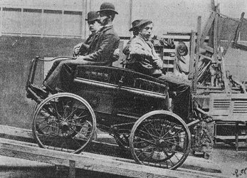
Figure 4. An oil-car climbing a gradient of
1 in 6. Courtesy of the late Jim Boulton. |
Figure 2 shows a view of the bottom of the small
double bogie car with axles turned to their extreme angle. We were
asked by the. London Electric Omnibus Company (Limited) to design
and build them an electric omnibus. They had made three or four
attempts, under Mr. Ward's direction, but had not been rewarded with
much success. I had already had some experience with the car
carrying nine passengers, and I went to London to see Ward's omnibus
run. The car that had run so successfully with us weighed 30 cwt.
unloaded, and carried nine people. |
|
Ward's omnibus weighed, with 24 passengers on, something like 7.5
tons. I saw that their difficulty was in the enormous weight, and
decided to build one not to exceed 3.5 tons, loaded with 14 passengers,
driver, and conductor (Figure 3). This was constructed on the
double-bogie principle having the batteries under the seats. It has two
motors, one on each bogie, driving all four wheels. To each of the four
wheels has been attached a powerful hydraulic brake, worked by means of
a force pump near the driver's seat. The vehicle has three speeds
forward and one backward, it will turn in its own length, has only two
handles to manipulate it, and will run over ordinary roads 25 miles with
one charge at a mean speed of eight miles an hour.
Figure 4 shows an oil-car climbing a gradient of 1 in 6, upon which
it is just as easily manipulated as upon the level, stopping,
starting, backing, and going forward at the will of the driver, and
without the aid of a brake.
|
Return to the
previous page |
|
|