|
Description of the Installation
The Blackpool system is described as
electricity generated at a central station, and conveyed to the
cars by the medium of an underground conductor lying centrally
between the tram rails. The rails form the return circuit. The
cars are worked in parallel.
The Blackpool line is nearly 2 miles in
length. It is a single track, with ten pass-byes and one length
of double line. The engine house and car sheds are placed near
the centre; this position was selected as being the most
convenient, and offering considerable advantages from an
electrical point of view, compared with a generating station at
one end.
The roadway runs along the sea coast and is
exposed to the full force of the wind and tide from the Irish
Sea. So strong are the periodical storms that, though the road
level is well above ordinary high water mark, the waves dash
over in such volumes that the road is flooded.
The difficulties in applying electricity
underground in such a situation are therefore unusually great.
When the tide is over the line, the current, of course makes
earth. At one time it was intended to employ accumulators for
haulage during the flooding, and horses were occasionally used;
but owing to the amount of shingle brought over, the grooves in
the rail were filled, and the cars kept running off. Working
during the floodings has therefore been abandoned. These
circumstances pointed to the necessity of allowing any dirt or
shingle that might enter the slit in the surface of the centre
channel to fall through freely to the bottom, and also of
providing for its easy removal. The sump holes and traps for
this purpose are placed at frequent intervals, and have direct
drains connecting them with the sea.
The chairs are of cast-iron, 11 inches high
with a 12½ inch base, and an internal width of 5½ inches; the
bottom H rounded, and the ends have pockets for holding the side
boards. These chairs are placed every yard, and support the
steel troughing which is bolted to their surface; the nuts are
covered and locked by a cast-iron cap.
The rest of the troughing is filled with
wooden blocks. The sides of the troughs are inclined, so that
when fixed, the space between them is ½ inch at the top, and 1
inch at the bottom, the object being that any stone having once
passed the surface may easily fall through, instead of getting
hopelessly jammed. Creosoted wood is used for the sides, with a
view to adding to the insulation. The wood sides have a 2½ inch
hole bored midway between the chairs, for the reception of the
porcelain insulator; and ¾ inch holes are bored at right angles
for the insertion of a wooden peg, which, passing through the
groove in the insulator, locks it fast. This method has added
greatly to the facility of construction. The roadway under the
side-pieces is packed; the centre is concreted, and tooled to
form the same curvature as the bottom of the chair.
The conductors are made of hard drawn
copper, having a conductivity of 96 percent of pure copper. They
are in lengths of 36 feet, and weigh almost exactly 1 lb. per
foot.
A cross section of the conduit.
The tubes are connected one with the other
by wedges made of drawn brass, exactly fitting the inside of the
tube. Space is left between the ends to allow for expansion and
contraction, and the wedges are secured from shifting by a
wrapping of wire. The two tubes are electrically connected at
every hundred yards by U-shaped loops of insulated and lead
sheathed copper wire, placed in a groove that is cut in the
sides and bottom of the channel. Over each of these loops is
placed a hand hole, which is made by cutting both of the steel
troughs and filling the place with two pieces of yard length,
which are protected by suitable side plates. These hand holds
are needful for many purposes, especially for the insertion of
the scrapers used for cleaning the channels, and for the removal
of collectors, should they become damaged or require adjustment.
Only the positive electricity passes along the copper
conductors. The return circuit is made by means of the rails;
and to ensure its being electrically good, each rail is
connected by a strip of copper passing from rail to rail, and
plugged into holes punched in the ends.
Dealing with the points necessitated by the
numerous pass-byes was a matter of no small difficulty, for in
tramways it is desirable that the rail-points forming the
turn-outs should be as fine as possible, so as to avoid strains
and joltings of the car. In order to prevent the collector from
fouling when taking the points, the ends of the secondary tubes
are fitted with brass horns. Although the lay of the channel
points is such that the collector has no tendency to take the
wrong way, yet, for further security against such a mishap, a
steel spring is placed at the toe, which guides the collector to
the proper side in taking the points, and opens freely for
allowing it to pass when leaving.
The collector consists of three main parts,
namely, one centre-piece, and two clearing ploughs for enabling
it to run in either direction. One of the elements of success in
working electric tramways with conductors underground is the
employment of a flexible conductor, flexibly connected. For this
purpose the two ploughs are joined to the centre-piece, either
by a tempered steel strip, or by a hinged wrought-iron plate.
The tempered steel plates forming the ploughs are held by
cast-iron cheeks, and being placed at a proper angle extend
downwards a little past the bottom of the steel troughs; their
upper ends terminate in a prong or finger, curved slightly
backwards. The fingers receive the loop or ring of the hauling
ropes, which are attached to the front and rear of the car. The
ropes are strong enough to stand considerable strain, and their
ends are fitted either with a releasing clip, or with a short
loop of weaker cord, which is strong enough to bear the stress
due to any ordinary obstruction; but should an absolute block
occur, then the small loop breaks; or the slip lets go, and the
collector is left behind, while the car travels forward.
At the
same time the ring of the trailing rope slips off the finger of
the rear plough; if this were not so, the force required to
break the loop of the trailing rope would make the collector
kick up, and would cause the contact-making part of the
centre-piece to short circuit with the underside of the steel
troughing. The centre piece consists of a cast-iron cheek,
holding a plate of strong brass, which is thoroughly insulated
and protected by hardened steel guards where it passes
through the troughing. The bottom of the insulated plate is
bared of insulating material, and has attached to it either a
short plate of brass, or two brass wires forming a T, and
holding at each end hard metal wings specially prepared. The
forward wing is bent so as to press against the left-hand
conductor-tube, end the rear one is bent so as to press against
the right-hand tube. To the upper end of the insulated plate is
fixed a clip, surrounded by an india-rubber ring. The clip is
bored to receive a heart-shaped terminal, which can be easily
pushed into it, but requires a fair snatch to withdraw it. A
similar clip is fixed to the receiving wire under the car, end a
short length of curled insulated wire, with a heart-shaped
terminal at each end, makes a ready connection between the
collector and the car.
The track and conduit.
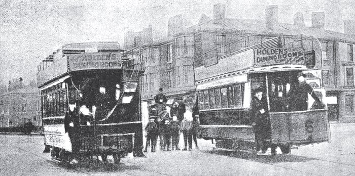
The cars are of various designs. The
smallest are light, open summer cars, seating thirty passengers.
The largest are provided with transverse seats on the roofs, and
carry fifty-six passengers. The levers of the ordinary chain
break are placed outside the wheels, so as to leave a clear
space under the centre of the car for the motor and the gearing.
The mechanical construction of the motor was specially designed
for allowing it to be fixed in position. The bearings are held
in a circular frame, large enough for allowing the armature to
be passed through it.
The motors are series-wound, and of such
proportions that they yield a high efficiency, running in either
direction, without giving any lead to the brushes. Reversal is
effected by changing the internal coupling, that is to say,
while the current through the field is always in one direction,
the current through the armature can be reversed, thus changing
the relative polarity and consequent direction of motion. Each
brush consists of a thin steel plate, insulated from the studs
and free to work on them. The steel plates are divided into
fingers, which carry little blocks made of a special metal, and
capable of being easily renewed. The blocks are made to press
against the commutator by small bands of india-rubber stretching
from tip to tip of the fingers. The pressure of the brushes is
thereby regulated and equalised, and the vibration and jolting
are compensated.
With regard to the gearing, it may be
explained that to the circular frame of the motor is bolted the
base of an elbow bracket, which carries the invert wheel-gearing
into a gun-metal pinion on the end of the armature spindle. The
box holding the invert wheel has upon its back a chain pinion,
from which the power is taken to the large wheel keyed upon the
axle of the car. The elbow bracket can be turned upon its base,
so as to either slacken or tighten the chain at pleasure,
without moving the motor or disarranging the centres of the
armature pinion and invert wheel. But for the inevitable
stretching of the chain, and the noise when new, this gear would
be all that could be desired.
The wiring of the cars is carried out as
follows: In order to control the quantity of current, and the
consequent speed resistance, coils are placed in certain
positions, and are coupled with the switch-boxes under the car
steps. A removable handle is used for driving, end a plug
fly-switch for reversal; these are in charge of the driver, and
when the car has completed its run in one direction, he carries
them to the other end of the car; this plan prevents any
accidental derangement, as it is impossible for the switches to
be worked without them.
Medium sized car, seating 48 passengers.
Underframe.
As the cars have to work all day, the
engines and dynamos are in duplicate, each being capable of
doing the full ordinary work, while in case of need both can be
used at once. The engines are 25 nominal horsepower, compound
none condensing, of the semi-portable type, with locomotive
boilers. A second motion-shaft is employed, in order that either
or both of the engines may drive either or both of the machines.
The dynamos are placed on a higher level than the engines, which
enables the wheels controlling the friction couplings to be
placed in a position where they can be worked conveniently by
the engineman.
Power station.
The generators are four pole shunt wound
dynamos; but, instead of allowing any current from their own
armatures to pass round the field magnets, these are separately
excited by the little machines. As the electro-motive force of
the external circuit varies directly with the intensity of the
field, it can be regulated to a nicety by varying the resistance
in the circuit of the exciter. This resistance is, by
preference, placed in the armature circuit of the exciter. The
maximum electro-motive force of the generators is 300 volts; and
each will yield 180 amperes. They can, when required, be run in
parallel. The total length of No. 17 wire (0.06 inch thick) on
the magnets of each generator is about 14 miles.
Measures were taken of the insulation of
the line during construction, and 150 yards length was found to
give 4,490 ohms. The average working loss through leakage may be
taken at 25 amperes, which at an electro-motive force of 220
volts is equal to 7.2 horsepower.
As the efficiency of the generators is
about 90 percent, and of the motors about 80 percent, much
further economy must be looked for in them, though it should be
possible for the loss of the generator to be not more than 5
percent, and in the motor 10 percent. The chief part in which to
look for further economy is the line itself; and in this, the
first point is more perfect insulation, and, consequently, less
loss in leakage; and the next is, more perfect continuity in the
conductors, and therefore less loss through resistance.
From the minutes of evidence
prepared for the Australian Parliamentary Standing
Committee on Public Works, for New South Wales. |
|