|
The Electric Construction
Corporation
When the new Corporation was formed, it purchased
and amalgamated the following companies and their patents:
| 1).
|
Elwell-Parker, Limited. Employing 400 people with
a large order-book. |
|
2). |
The Electrical Power Storage Company Limited, and
their Millwall factory, together with the company's many
electrical power storage patents. |
|
3). |
The Railway Electrical Contractors Limited, and
their patents and contracts for train lighting. |
|
4). |
The Julien Patents for Electric Traction, the
Sprague Patents for Electrical Traction and the Transmission of
Power. |
The starting Capital of the Corporation was
£500,000 in 50,000 shares of £10 each. Numbers 1 to 100 inclusive
were Founder’s Shares. The new concern was incorporated on 7th
June, 1889, and it was decided to build a new works on the land
already purchased by Elwell-Parker at Bushbury, along with some
adjacent land. The new works were erected at a cost of £10,000 on
the 24.5 acre site. When the building work was complete, the staff
and machinery from Commercial Road were moved to the new site. On
16th June, 1890 the Commercial Road factory was sold to the Electric
Construction Corporation. Presumably the E.C.C. continued to use the
works for some time, as the factory remained in the company's
ownership until 12th March, 1895 when the buildings were sold to
Thomas Brotherton and Francis Simms.
A description of the new works appeared in the Midland
Counties Express, on Saturday, 9th August, 1890, part of
which is as follows: |
|
The Electrical Works at Bushbury
Elwell-Parker machinery can be found in
every civilised country in the world, specially adapted to the
requirements of the transmission of power and electro-chemical
purposes. Elwell-Parker Limited is now part of a syndicate
called the Electric Construction Corporation. The business of
the firm recently assumed such immense proportions that it was
found necessary to acquire more commodious premises in which to
carry out the work of the concern.
Land was acquired in Showell Road,
Bushbury, and a new factory was built there. It is due to be
completed next month and will employ a large number of people.
There is one man above all others to whom the credit must be
given for introducing and developing this trade, and raising
Wolverhampton to a position of importance in the commercial
world, which this town would otherwise not have attained, but
for his skill and enterprise, and it is to Mr. Thomas Parker. |
 |
It was resolved in 1887 to erect new premises in
Bushbury, and a portion of the land was purchased for that purpose,
however, when the concern was taken over by the present company, the
Electric Construction Corporation, Limited, it was resolved to build
on the site first proposed but on a larger scale. Employment is
found in the present works for about 600 hands. Large orders are in
hand, and work assured which will fully occupy the new works, and it
is expected that 2,000 hands will soon be employed. In this concern
Mr. Parker holds the position of chief engineer and works director.
Honours have also been thrust upon him. In 1885 he was made a member
of the Institution of Electrical Engineers, and in 1889 a member of
the Institute of Civil Engineers. |
|
At the new works the machinery is bolted down
into the concrete foundation and upper columns carrying the roof
trusses have a specially designed head, which allows the
rainwater from the roof to flow down the columns to a drain at
the bottom. A siding from the L.N.W.R. is brought into the
works, and runs across the shops at the top end, so that the
electric overhead travelling cranes can deposit goods upon the
trucks for removal from one shop to another, or for sending them
away. There will be two 10 ton travelling cranes in a 45 ft. bay
and two identical ones in the foundry. The remaining five bays
of the main shop are fitted with 5 ton cranes worked in the same
way. The siding is also taken to the foundry cupolas and boiler
house. The office windows overlook the shops and yard and there
is an enquiry and a timekeeper’s office in-between the workmen’s
entrance and the main entrance, so that the timekeeper can see
everyone who enters or leaves the premises. There are two
waiting rooms for the offices, one for the works, and a
consulting room adjoining Mr. Parker’s office. There are three
large offices for the secretary, electrician and chief
draughtsman. There is a strong room lined with fire brick and
fitted with Chubbs’ patent fire and thief-proof door, which
opens from the secretary’s office.
There is a large board room, telephone room,
storeroom and typewriter room close to the clerk’s desk. There
is a photographic room for copying drawings, a pupil’s room,
which is entered from the works, separate lavatories, a cloak
room and a clerk’s dining room. The drawing office and clerk’s
office are each 32ft. by 34ft. 6 inches and are partly lit from
the roof. There is a corridor leading from the clerk’s office to
the works so that instructions can be given to workmen and
enquiries for drawings etc. can be made without disturbing the
main office. A covered passage also leads from the offices to
the warehouse. The engine house, which is 35ft. square and the
boiler house, which is 78ft. by 45ft are built on the east side
of the main shops.
The boiler house is 7ft. 9 inches below the
level of the main yard and contains seven Babcock and Wilcox
boilers. Projecting from this and under the yard are coal
bunkers with a siding passing over them so that coal can
immediately be shot-down to the level of the boilers. The
circular chimney stack is 120ft. high and 8ft. internal diameter
at the bottom, tapering to 6ft. 8 inches internal diameter at
the top, with a large moulded cast-iron cap. The laboratory, on
the left-hand side of the gateway into Showell Road measures
56ft. 6 inches by 20ft. and consists of chemical and physical
departments, separated by a glass screen. There is a small 20ft.
by 10ft. room which is used for rough work and the storage of
batteries. The laboratory has a number of porcelain sinks,
specially designed tables and fume closets.
The pattern shop and storeroom each measure
100ft. by 33ft. 6 inches and extend along Showell Road, just
above the laboratory, and have suitable workbenches for the
construction of patterns. The iron foundry measures 160ft. by
82ft. 2 inches and the brass foundry measures 62ft. 2inches by
40ft. They stand on the opposite side of the siding to the
pattern shop and are similarly constructed to the large shops,
with columns, girders and cranes etc. and have temporary ends so
that they can be extended if required. Three large drying stoves
are provided with specially designed furnaces and there are two
of Thwaite’s patent rapid cupolas with a lift and charging
platform, each capable of melting 5 tons per hour.
The blacksmith’s shop, built alongside the
iron foundry measures 84ft. by 30ft. and is designed for 12
forges, and the latrines and water tower and tank are built
between the main shops and the foundry. The water tank is 20ft.
6 inches above the ground and holds 35,700 gallons. Water is
pumped into it from the brook, which runs through the site. It
will be used for supplying the boilers, sinks, lavatories etc.
The mess rooms consist of two large dining
rooms, one 70ft. by 40ft. for men and another 40ft. by 30ft. for
women. In between is a kitchen, measuring 25ft. 3 inches by
32ft. 3 inches. It is fitted throughout by the Coalbrookdale
Company, with a large range and grill, vegetable steamers, and a
hot closet so that workpeople can bring their own food and have
it warmed-up. There are lavatories on each side of the entrance
and each person will have his or her own place and number with a
coat-hook.
The site occupies about 24 acres, with yards
paved in tarmac covering about 4.25 acres. The bricks for the
general work came from the Tibbington brickworks, the blue
bricks came from Hockley Hall Company and the facing bricks for
the offices and mess rooms were supplied by Messrs. Partridge
and Company of Kingswinford.
Over the main entrance to the offices is an
ornamental clock tower, with stone dressings. The pilaster and
moulded pediment over the entrance doors, and all exterior
stonework are executed with white Hollington stone. The office
roofing tiles were obtained from the Hockley Hall Company and
the other roofing tiles are of best Bangor slate. A large
proportion of the roofing area is glazed on the simplex system
and the main shops are paved with patent granitic flooring. The
laboratory floor is made of wooden blocks set on a concrete
foundation and the office corridors are laid with Ebner’s
Terrazzo Mosaic with a coloured glazed brick dado with moulded
capping four feet high. Most offices are heated by open
fireplaces, but the large drawing and clerk’s offices are warmed
by hot water on a low pressure system, the boiler being placed
in the basement in a separate room. The mess rooms are also
heated on the same system. The large shops will be heated by the
exhaust steam from the engines, carried in 4 inch pipes between
the columns. |
|
|
An attempt was made to make Thomas Parker a
director of the new concern6,
but this was defeated and he had to be content with the post of
Works Manager.
The Corporation got off to an excellent start under the
chairmanship of Sir Henry Mance. The works were operating at
full capacity and orders flooded in, including a further order
from the Birmingham tramways, following the successful running
of the Elwell-Parker prototype. In the battery-powered vehicles,
the accumulators were placed under the passenger's seats, and a
portion of the gross profit was absorbed in the settlement of
claims from passengers, whose clothing had been splashed by
acid.
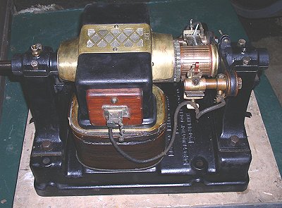
In 1890 two Elwell-Parker type dynamos were displayed at the
Paris Exhibition. They were driven by two Crossley 'Otto' gas
engines, and supplied power for lighting.
One of the dynamos sent to the Paris
Exhibition.
In 1890 another Elwell-Parker type dynamo was
displayed at the Edinburgh International Exhibition on the
Carrick and Ritchie stand. It was operated by a Carrick and
Ritchie 'Waverley' water turbine. The firm supplied the turbines
with the Elwell-Parker type dynamos for lighting installations
in large houses or factories.
Many of Thomas Parker's designs were ahead of
their time. In the 1880's a number of power stations were built
for electricity distribution. They all used D.C. because of the
difficulties involved in running A.C. generators (alternators),
in parallel. When a number of alternators are connected in
parallel, each one must be synchronised to the others, so that
all of the outputs are in phase. This was first achieved
experimentally by Dr. Hopkinson in 1886, but was not put into
practice until 1891. This is an essential requirement for modern
electricity distribution. The first two installations using this
technique were at Bournemouth, using Mordey alternators and at
West Brompton using Parker machines. Another year passed before
A.C. generation came into general use.
In 1890 the E.C.C.
granted a licence to the General Electric Power and
Traction Company of Kentish Town, London for the use of its
traction patents. The firm also agreed to supply the traction
company with accumulators. By 1893 Thomas Parker was a director
of the traction company.
|
| |
|
| Read about phosphorus
production and Heath Town works |
 |
| |
|
|
E.C.C. also developed an overhead-wire, tram
system, which was put to use in 1893 when the company
electrified the South Staffordshire Tramways and a little
while later the Hartlepool tramway. Thomas Parker laid-down
a section of tram-line at the works, which he hoped would be
largely copied in London for direct tram-driving. |
| |
|
| Read about the South Staffordshire
Tramways |
|
| |
|
|
The E.C.C. received another order for an 800 ampere-hour battery, for the
Whitehall Court in London, followed by possibly the most important order
at the time, for the electrification of the Liverpool Overhead Railway.
This was the earliest and only example of an elevated electric
railway in the country. The project was a great success, and in
1900 the company undertook the re-electrification of the City
and London Railway.
Read about the
Liverpool
Overhead Railway |
|
Another important order was the planning and installation of
the Oxford Electric Company's Works, which was so successful
that it became known as "The Oxford System" of electrical
transmission. The E.C.C. specialised in direct current high
tension, and their "Oxford System" included a central generating
station, supplying 2,000 volts D.C. into sub-stations, where
motor-generators stepped the voltage down to 200 volts. The same
system using a central supply of 1,000 volts was used at
Birmingham, Charing Cross, Chelsea, Sydenham and Shoreditch. The
company also installed the electricity generation and
transmission system for lighting at Burnley.
|
The
Crystal Palace Electrical Exhibition. The Engineer, 1st
April, 1892.
The present exhibition at the Crystal
Palace will mark the successful operation of one of the most
practical modern schemes for the distribution of electric
current over wide areas. The continuous current transformer
has here asserted itself, and proved that with carefully
worked out details in construction, and in the system with
which it is used, it is a most trustworthy and
efficient means of securing the advantages of a high tension
distribution with a continuous current supply. No
undertakers who find themselves called upon to extend their
low tension mains into remote suburban districts need fear
that because they do not happen to be using alternating
currents, they must either bear the cost of additional
stations to feed the network or sink excessive amounts in
mains.
The entire system has been worked out
on a practical basis by the Electric Construction
Corporation of Wolverhampton under the guidance of Mr.
Thomas Parker, the works director, and one of the most
pleasing exhibits in the exhibition is to be found in the
stand of this Corporation in the Machinery Court, containing
as it does machines of such high-class construction, and
controlling apparatus so well suited to the requirements of
the system.
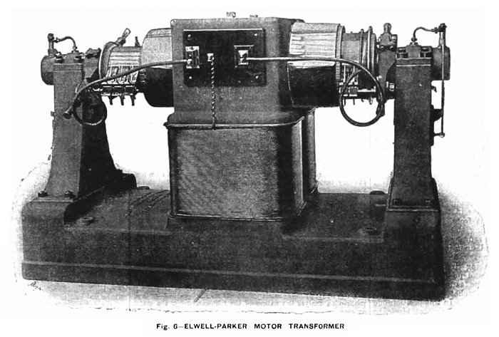
The largest machine in this stand, Fig.
6, is a continuous current transformer or motor transformer,
identical in size and output with the ten machines used
inside the Palace for the supply of current to exhibitors.
It is to be regretted that it was found necessary to fix
these machines so far out of sight underneath the Palace, as
otherwise their full display in operation would have
considerably added to the practical interest of the
exhibition.
We have already explained the working
of the machines in the Palace, which receive current at
1,000 volts pressure from the Crystal Palace and District
Electric Supply Company’s Station at Sydenham, one and a
quarter miles distant, and transform it down to a pressure
of 110 volts for exhibitors. The complete system of
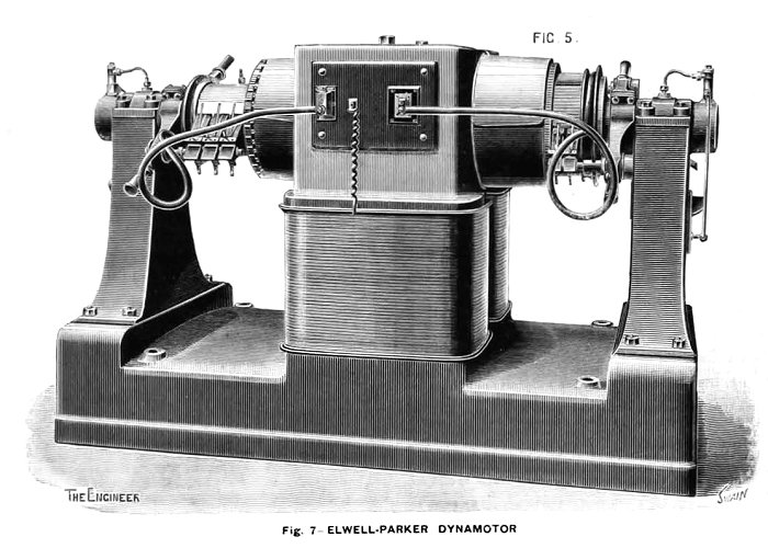
distribution by these motor transformers for town lighting,
as now adopted at Oxford, will be understood by reference to
Fig. 7.
In the first place there is the
generating station, the site of which is selected with
reference to good water supply and economical facilities for
delivery of coal. In this station are installed the
necessary engines and boilers, together with the electric
generators and their exciters. As the area of lighting
extends, more generators can be added, their manipulations
in parallel being perfectly simple. These produce current at
1,000 volts pressure, which is delivered by all the machines
on to one pair of bars in the station, known as omnibus
bars, or shorter, bus bars. From these the current proceeds
along the high tension mains to the most central point in
the district of supply, at which is located a central switch
station.
From this station is controlled the
working of all the transformers used in the system, these
machines being located in sub-stations situated radially
around the switch station at points most favourable for
feeding the low tension network of supply, and keeping the
electric pressure uniform throughout. At the switch station
there is a pair of omnibus bars receiving the high tension
current from the generating station, and from which the same
current is, through double pole switches, connected onto the
feeders supplying the motor transformers at the
sub-stations. For the complete control of all the
transformers only one man is required in the switch station.
The voltmeters in this station show the
pressure on the town supply network at all the sub-stations,
and as the load increases in any district, the pressure is
kept up by switching on an additional transformer located in
that district. Although the sub-stations where the
transformers are fixed are at various distances away from
the switch station, the switching in or out of these
machines controlled by one man at the above station with
perfect certainty and ease.
In performing this operation the first
thing to do is to close the two-pole switch which conveys
the high-tension current to the transformer. The current,
which passes through a considerable resistance before
leaving the station, passes into the armature of the machine
on the high-tension side, and excites the field through a
few turns of thick wire in series. The brushes on both
commutators are kept permanently down, and need no
alteration of lead for changes of load, as the reactions of
the two armatures neutralise one another. Once the
excitation of field is started, the machine starts, at first
quickly, but the shunt field rapidly building up, the speed
soon decreases again, and is then brought up to the required
amount by reducing the main resistance in the switch
station. So far the transformer is started, but the
secondary winding on the armature is not yet put in
connection to feed the supply mains. This is done at the
switch station by the simple act of momentarily closing and
opening a switch which short-circuits the voltmeter. This
causes a current to flow through an automatic circuit closer
fixed with each transformer in the sub-station.
This apparatus, shown in the figure,
consists primarily of an iron-clad electromagnet, the
exciting coil of which is included in the circuit of the
voltmeter at the switch station. The resistance being small
does not interfere with the voltmeter readings, and,
moreover, by short circuiting the voltmeter in the switch
station for an instant, a large current from the supply
mains flows through the coil, causing the armature of the
magnet to be drawn up. The armature carries two pawls lying
on a ratchet wheel, and upon its being attracted upwards,
the left-hand pawl engages one tooth and moves the ratchet.
Again, on breaking the short-circuit
the armature falls, and the right-hand pawl engages, forcing
the wheel round further in the same direction. The double
operation moves the ratchet wheel and cam through one-eighth
of a revolution. In this position one tooth of the cam bears
down on the contact block, so completing the low tension
circuit from the transformer to the mains. The load on the
mains is equally divided between the transformers at work,
but in case of short circuit or any accidental stoppage
which would cause an undue rush of current into the machine,
an automatic cut-out, shown at M is fixed in connection with
the above apparatus. The armature of the electromagnet M
would in such an event be drawn up and strike the cam,
shifting it round and disengaging the tooth from the contact
piece S, thus breaking the circuit.
Similarly, as the load decreases, the
various transformers can be severally disconnected from the
supply by the operator at the switching station. Once
closing and opening the voltmeter switch shifts the cam
another eighth round, and allows the contact piece S to rise
and break circuit.
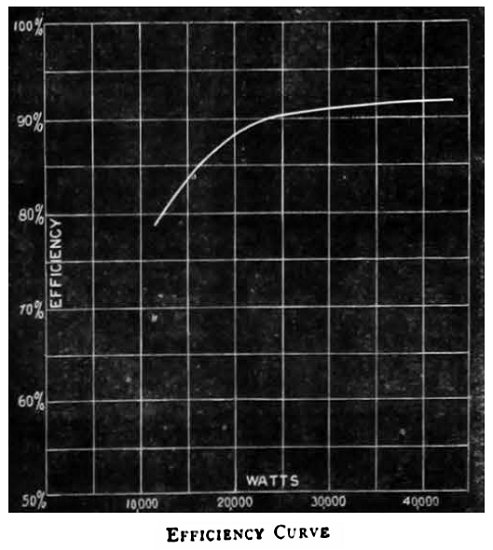 |
By this arrangement the transformers are only
used as the load requires, and are therefore, for
the greater part of the working time, near their
full load; and as the efficiency of these machines
reaches 92 percent when delivering their full load
of 40 kilowatts, and 87 percent at half load, see
curve, Fig. 8, it will be seen that the whole system
is worked with great economy. The only regulation
required in the generating station is the adjustment
of the strength of exciting current supplied to the
generators, the pressure, as indicated by a
voltmeter on the omnibus bars in the station, being
maintained constant by this means. The exciting
current is regulated by resistance in the shunt
field of the excitors, of which there is a separate
machine for each generator. |
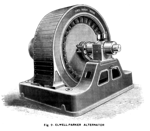
The Corporation have also carried out
several important contracts in alternating current plant. We
illustrate the Elwell -Parker alternator, Fig. 9, of 80
kilowatts, as exhibited in operation at the Palace. The
armature is a stationary external ring, built up of soft
iron rings, to the inside surface of which are clamped the
coils. The latter are twelve in number and composed of
copper strip, the edges being placed radial to the machine.
These are held by wooden clamps bolted round the ring on
each side. The field magnet, with the same number of coils,
mounted on cores and yoke of solid forged iron, rotates
inside the armature. The machine being high-tension, the
armature is externally cased-in with a wooden cover, and the
terminals of the machine are protected under a portion of
this cover, kept under lock and key. The wires leading from
these terminals are also taken underneath the bed of the
machine in casing through the concrete, so that complete
immunity from danger is attained.
Alternate current transformers of 2 and
4 horse power output are also shown in Fig. 10. These are of
very simple construction, the two circuits being first bound
together and afterwards encased around with soft iron plates
made in the form of the letter L and built up on each side
of the coils. The two rows of discs are then clamped
together by bolts passing through cast iron end pieces.
The Corporation also exhibit a new
pattern of adjustable resistance, sets of cut-outs fitted in
porcelain boxes, and a high tension automatic switch used in
connection with the above transformers. |
|
|
Electric Lighting in Oxford. The
Engineer, 1st July, 1892.
On Saturday, June 18th, the electric
current was switched on for the first time to the City of
Oxford, by the Oxford Electric Company, and a large party
had been invited to a dinner given at the works in honour of
the occasion. The arrangements were very satisfactorily made
by Mr. George Offor, the secretary of the company. We have
referred previously in our issue of April 1st last to some
of the features of the system employed, and are now able to
give a full description of the plant.
It was found impossible to obtain a
suitable piece of ground for the works near the centre of
the city, a piece of land was therefore acquired at Osney
upon the banks of the River Isis.
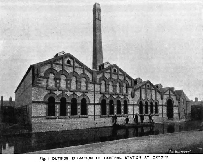
The outside of the building, which are
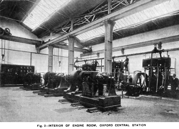
of a neat design in brick, is shown in Fig. 1. The interior
of the engine room is shown in Fig. 2, from which it is
evident that there is ample room for more plant. This
position will enable the company to charge electric
launches, which will be an important source of revenue, and
the works are kept away from the better parts the town.
The
system adopted is that of high-tension continuous currents,
with dynamotors or current transformers, which produce
currents of low pressure for the network. The dynamos at the
generating station produce the current at a pressure of
1,000 volts, and this is transformed down at the sub
stations to a pressure of 100 volts. Fig. 3 is a plan of the
part of the city in which the substations are placed, and
the mains already laid along the streets are shown.
The
contractors for the whole work are the Electric Construction
Corporation, of Wolverhampton, and it has been carried out
under the supervision of Mr. Thomas Parker, the managing
director. The building is a well built structure of brick,
designed by Mr. Brevitt, of Wolverhampton, and the builders
were Messrs. Kingerley, of Oxford.
It is divided into two main sheds,
separated by a brick wall. The engines and dynamos are
placed in one part, and the boilers in the other, and all
the plant is on the ground level. The engine room is thus
kept perfectly free from coal dust. Three steel boilers of
the locomotive type are at present installed; these were all
built by Messrs. J. and H. McLaren, of Leeds; a Green's fuel
economiser is placed in the main flue and a suitable by pass
is arranged so that gases may pass direct to the chimney if
needful.
The engine room is well lighted from
above. The steam pipes are arranged upon the ring system, so
that in case of breakdown, as little as possible of the
plant would be affected. Stop valves are placed between each
two engines, and the bends are all of copper. Three engines
are now put down, and these are of the inverted
triple-expansion type, built by Messrs. J. and H. McLaron
and Co. By the courtesy of the makers we are enabled to give
the results of tests which were carried out at the works by
Mr. Wilson Hartnell, Professor Goodman, and the inspecting
engineer, Mr. Watson. The sizes of the cylinders are:-
high-pressure, 9in. diameter, intermediate, 14·25in.,
low-pressure 22·5in. diameter, by 24in. stroke.
Two trials
were made, in one of which it will be observed the steam
jackets were used, an in the other were not used. We may add
that the high-pressure and intermediate cylinders are jacketted with steam at boiler pressure, and are drained
through a McDougal steam trap into the hot well. The
low-pressure cylinder is not jacketted. The McLaren
automatic governor is placed inside the fly-wheel upon the
shaft itself, and it works direct on to the high-pressure
slide valve, which is not balanced in any way. The governor
is self-locking, and is therefore not affected by any
friction on the slide valve. The engines run very steadily,
and all danger of the governor being put out of gear by the
breaking of a belt is obviated. The surface condenser
is fitted with brass tubes and tube plate; the tubes are
⅞in. outside diameter, and there is 382 square feet of
cooling surface.
The air pump is 11½in. diameter, the
circulating pump 10in. diameter, and the feed pump 1¾in.
diameter, all three having a stroke of 14in. The pumps are placed behind the
condenser, and are worked by levers from the intermediate
engine. The crank shaft is of forged steel, 5¼in. diameter,
the crank pins 5½in. diameter, and the engines are
thoroughly well finished. Each of the engines is provided
with a heavy fly-wheel, and drives a dynamo by means of
belting; two of the belts are of the usual double-sewn type,
and the third is a Gaskin link belt.
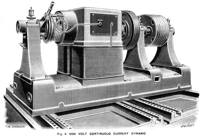
The three dynamos, one of which is
shown in Fig. 4 are all similar, and were built by the
Electric Construction Corporation; each develops 1,080 volts
and 80 amperes, when running at 400 revolutions per minute.
The dynamos are provided with an extra bearing outside the
driving pulley, and each is excited by a small Elwell-Parker
dynamo, driven from a rope pulley keyed on to the shaft of
the main generator. The exciters give 135 volts, and can
thus be used to charge the accumulators which are used for
lighting the central station.
The electro-motive force of the dynamos
can be regulated from 1,100 volts at full load to 1,000
volts at light load, by means of resistances placed in
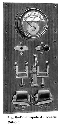
circuit with the exciters. In the circuit of each dynamo is placed
a double pole automatic cut-out, shown in Fig. 5 which
protects the dynamo in the event of any excessive current,
and is reset by hand, but it is so arranged that the cut-out
cannot be held on. The dynamos are all connected in parallel
to two common omnibus bars upon a switchboard at the works.
The foundations for the engines are of
a solid block of concrete, and that for the dynamos another
solid block, weighing about 100 tons each, and about 11ft.
deep. Air spaces are left round the blocks to diminish
vibration.
The switchboard at the works is very
simple, and consists of three panels, each of which is
similar to Fig. 5, and carries one ammeter for the high
tension circuit, one for the exciter circuit and the
knocking-off switch previously alluded to.
 |
Two overhead cranes, each capable of
lifting six tons, are provided in the engine house, and a
battery of fifty three E.P.S. cells is used for the lighting
of the station. By means of this battery and of that at the
chief sub-station, it is possible to shut down altogether at
the works for six to eight hours in winter, and twelve to
sixteen hours in summer. At the time of our visit, Mr.
McLean, the engineer in charge, had placed a dynamotor in
the works in order to light up about five arc lamps of
fifteen amperes each, and 370 eight candle-power lamps.
Current was also supplied for the electric cooking, which
formed a feature of the dinner.
From the generating station run out two
pairs of heavily insulated Silvertown cables, each
consisting of 37/14 copper wires; these are laid in
cast iron pipes, and are carried a distance of about
one mile to the distributing station at Broad Street
marked No.1 on the plan, Fig. 3.
The system of working is clearly shown in
diagram-Fig. 6 which we published in a previous
issue. It will be seen that the dynamos are coupled
to two omnibus bars at the generating station, and
thence run the high-tension mains to the central
switch station, whence all the other sub-stations
are controlled. |
At each of the
stations, Nos. 1, 2, and 3 on the plan Fig. 3, is placed a
dynamotor, such as shown in Fig. 7, which transforms the
pressure from 1,000 volts to 110 volts, and gives out a
current of 360 amperes when fully loaded. The efficiency of
these machines is very high, being 92 percent when fully
loaded, 89 percent at three quarters load, and 87 percent at
half load. The main winding is a shunt to the low-tension
side, and there are a few turns on the magnets in series
with the high-tension armature. The oiling arrangements are
very complete. The end of the armature shaft is provided
with a cam, which actuates the piston of a small oil pump
which feeds the bearing; the oil passes away through a
filter to the oil reservoir, and is used over again. It is
thus possible to run for some days without attention. The
brushes upon the commutator are of copper gauze.
An accumulator of 114 cells of the L.
31 E.P.S. type is installed here, and the cells are arranged
in four groups, two of thirty-eight cells and two of
nineteen cells. They are charged in three groups of
thirty-eight cells each, and are discharged in two groups,
each consisting of thirty-eight and nineteen cells in
series, and are capable of supplying a current of 120
amperes for eight hours.
|
Voltmeters are provided at the central
switch station, which show the pressure at each of the
sub-stations, and all the transformers can be controlled by
one man. In starting a transformer the high-tension circuit
is first closed through a resistance in order not to injure
the armature windings.
The dynamo field is then excited by a
few coils in series. The dynamo part then begins to produce
current, and the resistance is gradually taken out of the
high-tension circuit.
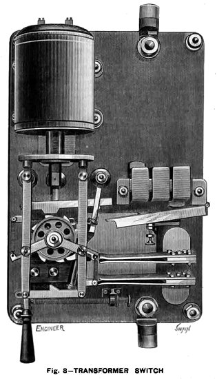
In order to put the transformer into
circuit with the low pressure network, a special apparatus
has been designed, shown in the diagram and also in Fig. 8;
this instrument is placed at the sub-station and is designed
for 400 amperes.
It consists of a long-pull electro-magnet,
which actuates a ratchet wheel and controls the switch. It
is actuated by merely closing and opening a switch which
short circuits the voltmeter on the pilot wire. One of the
wires to the voltmeter is wound round the long-pull magnet,
and the feeble current passing to the voltmeter under
ordinary conditions is not sufficient to attract the
armature, but by closing the switch the voltmeter is cut out
of the circuit, and the long-pull magnet acts; the switch is
then opened, the heavy armature drops, and the double
movement causes the switch which connects the low-tension
network to the transformer to close. In cases of accidental
overloading, an automatic cut out-shown in Fig. 5 opens the
circuit.
|
 |
The present capacity of the entire
plant is 12,000 lamps of 32 watts, and 15,000 lamps could be
wired. The low-tension mains were manufactured and laid by
Callender's Bitumen Telegraph Company, under the
superintendence of their engineer, Mr. W. Douglas Reid.
Those cables are of two sizes, half a square inch and a
quarter of a square inch section, and are of the
lead-sheathed type, armoured with two layers of steel tape.
These cables are simply laid in a trench under the footway,
at a depth of about 18in. They are laid in lengths of from
150 to 200 yards, and are connected together in cast iron
joint-boxes by means of copper connectors. The box is then
run in solid with bitumenised wax compound. Disconnecting
branch boxes are provided at different points in the network, so
that any section or street can be cut out without in any way
interrupting the supply to the rest of the network.
House service wires are connected in T
boxes by means of T copper connectors. These boxes and
connectors are so made that the cable is not out, but is
simply bared down to the copper strands and the connector
put on and soldered. The box is then run in solid with the
bitumenised wax compound. The small service wires are of two
sizes, seven fourteenths and twelve fourteenths, lead
sheathed and armoured. The arc cables are similar, but seven
sixteenths. The whole installation is a very interesting
example of the possibility of using high-tension continuous
currents for large areas.
|
|
High Tension Continuous Current Switchgear. The Electric
Construction Corporation, Wolverhampton. The Engineer 31st
March, 1893.
|
The switchgear illustrated by the
accompanying engravings are those used by the Electric
Construction Corporation, Wolverhampton, for their high
tension continuous supply system, as used at Oxford, and at
Sydenham.
The system consists in supplying a
system of distributing mains with current from a number of
motor generators situated at sub-stations, these being
supplied with current by high tension feeders run directly
from switchboards at a central station. Each transformer has
a separate feeder, and a pair of pilot wires also come back
from each sub-station. The starting, stopping, and
controlling of the motor generators is carried out from the
central station.
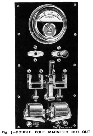
Fig. 1 represents a double-pole
automatic magnetic cut-out and main switch, which is coupled
on to the main omnibus bars at the central station, and from
which feeders running between the transformers are
connected.
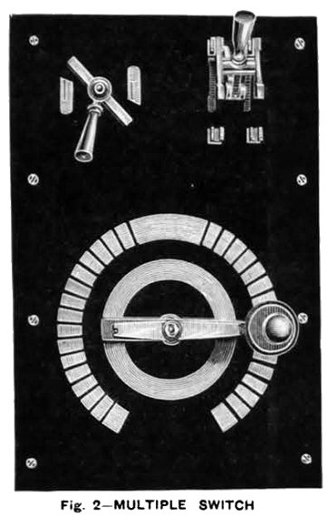
Fig. 2 represents a multiple contact
switch for cutting resistance in or out of the high-tension
feeder circuit. To start a transformer the multiple-contact
switch - Fig. 2 - is turned over, so that all resistance is
in circuit. The automatic cut-out- Fig. 1 - is then put on
so that the high tension current passes to the motor
generator at the sub-station. |
 |
 |
A few turns of thick wire wound round
the magnets in series with the feeders gives the necessary
magnetic field, enabling the motor generator to start. The
secondary or low tension then gradually magnetises the motor
generator field up to its full strength by a shunt across
the low-tension armature.
The starting resistance, which is
connected to the right-hand side blocks of the multiple
contact switch, Fig. 2 - is then taken out of circuit. The
small quick-break switch, shown at the top left hand corner
-Fig. 2 - is then closed, which short circuits the pilot
wires running back from sub-station, and one of these, wound
round a pot magnet, actuates a special transformer switch,
which connects the low-tension armature of the motor
generator on to the distributing mains. This switch is then
again broken, as only a momentary current is necessary, the
switch being held in either an on or off position by
springs.
A voltmeter is connected across the
pilot wires so as to indicate the electro-motive force on
the network at the feeding point. The regulation of this
electro-motive force is carried out by the left-hand blocks
of the multiple-contact switch - Fig. 2 - cutting resistance
in or out of the circuit. |
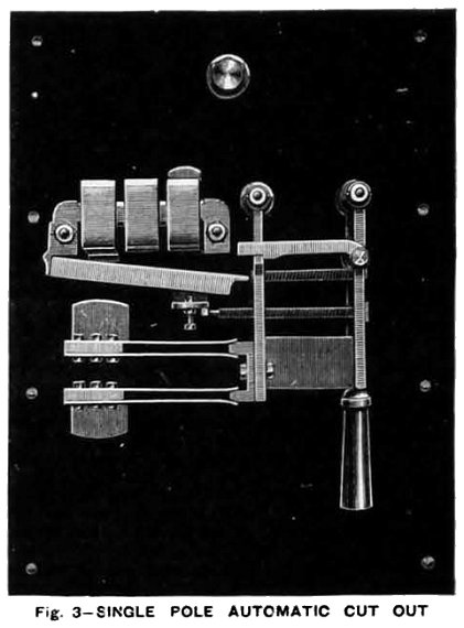
| Fig. 3 represents a single-pole automatic magnetic
cut-out, as is used at Oxford on the low tension of
transformers, situated at the central station, where they
can be reset by hand.
These cut-outs break circuit in event of an excessive
current being demanded by a short circuit on the mains.
The magnet is compound-wound, so that in the event of one
of the motor generators failing to give proper
electro-motive force, the current passing back from the
mains cuts out at a much smaller number of amperes, so as
not to cause an excessive demand from any other motor
generators that may be on the circuit, which is a thing that
always happens where ordinary fuses are employed; any fault
due to one machine failing to give its electro-motive force
usually melting the fuses of other machines that may be
connected in parallel on to the same circuit, owing to the
large current required to cut out the machine that has
failed. |
 |
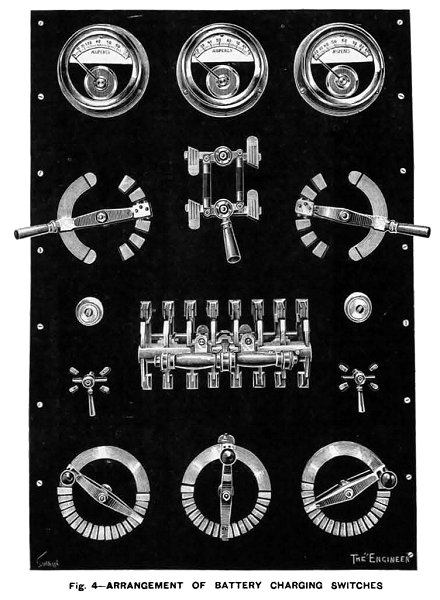 |
Fig. 4 represents an arrangement for charging a battery
of accumulators from distributing mains. As these are kept
at a constant electro-motive force, it is necessary to
cut-up the battery into sections for charging. At Oxford
there are 120 cells. These are charge in sets of 40 each,
discharging in sets of 60 each. A throw-over switch in the
centre of the board enables this alteration to be effected.
Three multiple contact switches at the bottom of the board,
and three ammeters at the top, are connected, one in each of
the three series when charging.
Two multiple contact switches enable the number of cells
in the discharging circuit to be regulated, and a
double-pole switch is provided for cutting off the
accumulators entirely. The two-way switches are provided for
connecting the voltmeter across one or other of the
batteries. |
|
|
| Read about some of Thomas
Parker's railway locomotives |
|
Within four years the new company found itself in deep trouble
and was voluntarily wound up in July, 1893. It seems that there
was a lot of dissension amongst the Board of Directors, one of
whom was later convicted of fraud. It was immediately
reconstituted as the Electric Construction Company under the
chairmanship of Sir Daniel Cooper.
|
The E.C.C. works in about 1902.
|
The Financial Times of 6th
July, 1893 mentions that the debenture holders and shareholders
agreed to reconstruct the Electric Construction Corporation into
the Electric Construction Company. The capital will be
written-down from £879,260 to £650,000 as the assets are now
considered to be less than was previously stated. The ordinary
shareholders will receive two £2 fully paid shares in the new
company for each fully-paid £10 share in the old Corporation.
Preference shareholders will receive five fully paid, seven
percent, cumulative preference shares of £2 each (£10), for each
£10 fully-paid seven percent cumulative preference share, of the
Corporation. Holders of Founder’s shares are to receive two £2
fully paid ordinary shares in the new company, for each £10
Founder’s share in the Corporation. It will be seen that the
heaviest loss falls on the ordinary shareholders, but the
apparent loss of capital makes no real difference, because the
£10 shares are barely re-saleable at 30s.
| The E.C.C. dynamo
at Cragside.
It is pure Thomas Parker,
looking just like an Elwell-Parker product.
Courtesy of Robin Wright,
Engineering Warden, Cragside. |
 |
The Electrical Power Storage Company, one of
the founder members of the Corporation was originally purchased
for £150,000 and later sold to the Foreign and Colonial Power
Storage Company for £75,000 in shares.
Sir Daniel Cooper was greatly disliked by Thomas Parker and
five of his senior staff from Elwell-Parker. They all resigned
within a year of Cooper's chairmanship, and at the first A.G.M.
in September, he referred to Thomas Parker in such a way that
suggested that there was no love lost between them. Thomas
Parker himself referred to the directors as "all that coterie,
about whom the less said the better".
Read about the
presentations
made to Thomas's senior
staff on their departure from
the E.E.C. |
|
The Express & Star newspaper of 11th April, 1894, contains an
article about Thomas Parker's resignation from E.C.C. It
includes the following paragraph:
We understand that a new company will be promoted with Mr.
Parker as one of its members, for the carrying out of works of a
similar character in this district, which will be of such
dimensions as will add considerably to the manufacturing
interest of the neighbourhood.
Thomas's resignation was also reported in the May 1894 edition of
The Railway Engineer as follows:
Mr. Thomas Parker, M.Inst.C.E., who designed and carried out
the electrical plant and motors of the Liverpool Overhead Railway,
has resigned his position as works director to the Electrical
Construction Company, Ltd. Mr. Parker had entire charge of the works
at Wolverhampton since the formation of the Electrical Construction
Company. He has registered a new Company - Thomas Parker, Limited,
and has secured a very fine site for his works at Wolverhampton. We
are informed that Mr. A. B. Blackburn, M.lnst.C.E.
(lately with Messrs. Mather and Platt Ltd.), has been appointed to
the position vacated by Mr. Parker.
|
|
|
|
|
|
Return to
the 1890s |
|
Return to the beginning |
|
Proceed to the
General Election |
|
|